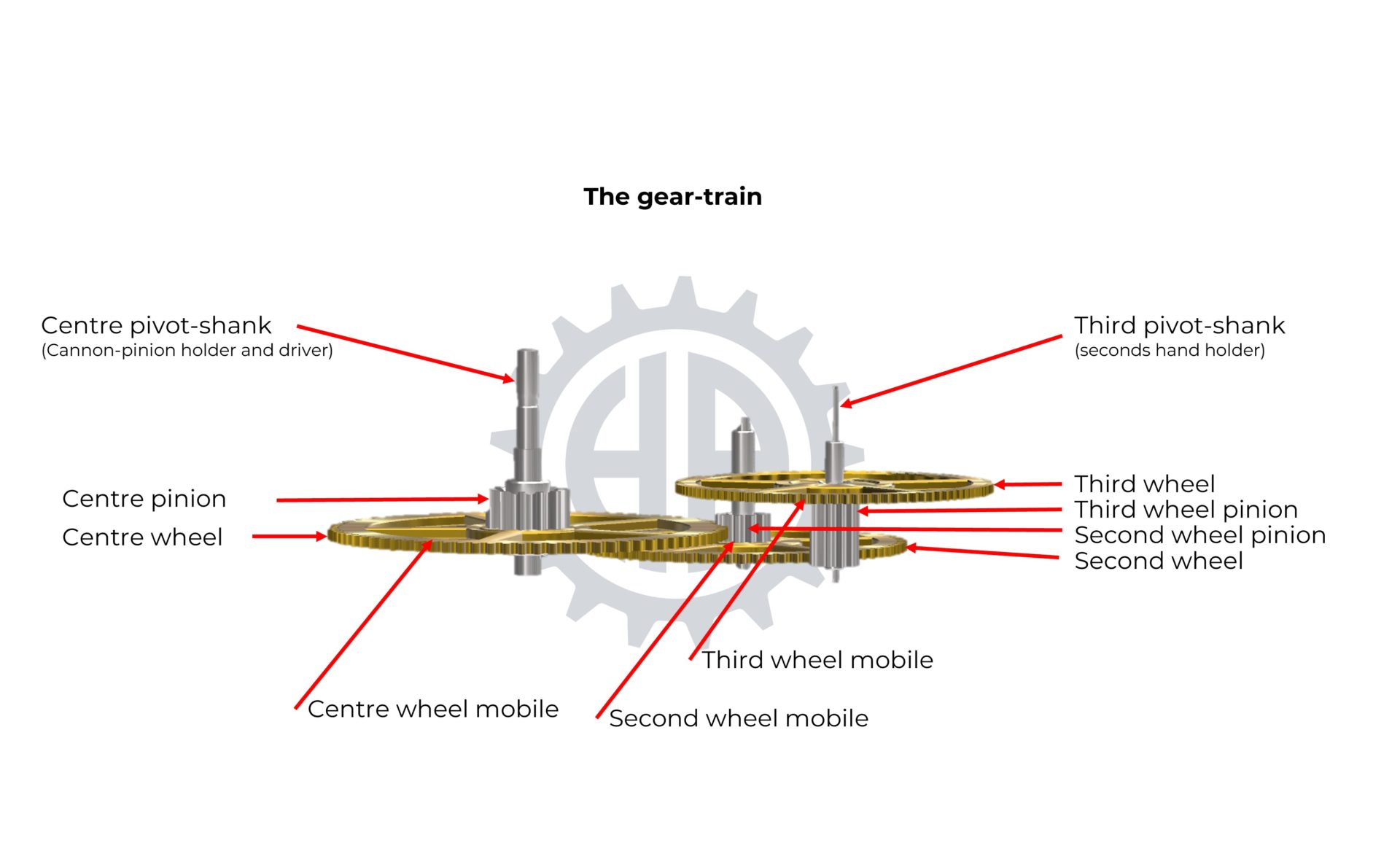
The gear train is the transmission mechanism of a movement. It consists of a variable number of gears, usually three. Its role is to transmit the energy from the barrel to the regulating organ through the escapement and to distribute information to the display (hours, minutes, seconds, etc.) through the different rotation speeds of its gears.
The Mobiles
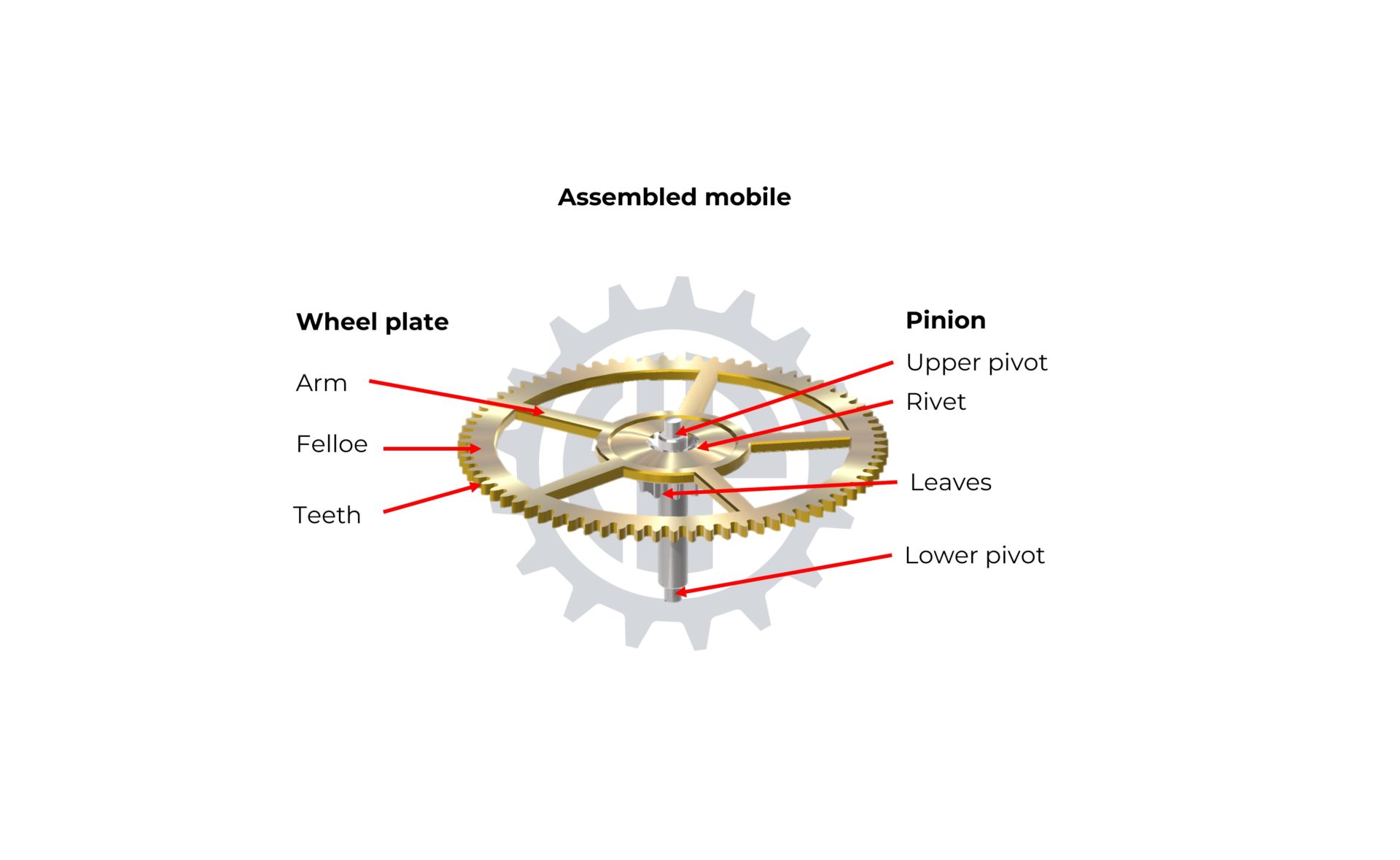
Each gear mobile consists of a steel pinion, whose teeth are called “leaves,” and a wheel (usually made of brass). The pinion is the axis of the gear, and the plate of the wheel is riveted to it and integral.
Thus, although they do not have the same number of teeth, when the pinion of a gear completes one full turn, the wheel of the same gear also completes one full turn.

Multiplying principle and Gear Ratio
The gear train is a multiplying gear, which means that each gear rotates faster than the one preceding it in the kinematic chain. This is achieved using the drive wheel-drive pinion principle. Each wheel drives the pinion of the next gear.
Example:
To understand, let’s take the example of a wheel with 100 teeth meshing with a pinion with 10 leaves. When 10 teeth of the wheel have engaged with ten leaves of the pinion, the wheel will have completed one-tenth of a turn, while the pinion it drives will have completed one full turn. This is referred to as a gear ratio of 10.
Calculating gear ratios allows assigning specific rotation speeds to each gear, depending on the frequency of the regulating organ.
The Wheels
The finishing gear train consists of at least three wheels:
- The centre wheel, which is directly driven by the barrel.
- The second wheel, which typically carries the minute hand. The calculation of the gear ratios ensures that this wheel completes one full rotation in exactly one hour.
- The third wheel, usually located at the opposite end of the finishing gear train, carries the seconds hand and rotates 60 times faster than the centre wheel, completing a full rotation in exactly one minute.

The principle of the gear train has existed since the dawn of mechanical watchmaking, and gears have always been built according to the same model: a brass wheel plate riveted to its pinion. However, pinions were made of iron until the mid-18th century when the first steel alloys appeared. The advent of steel allowed for much better results in terms of friction, wear resistance, and corrosion resistance. Besides alloy quality, the main historical developments primarily concern the tools and machines used for gear production, especially the definition of teeth profiles to limit friction and energy losses. Modern teeth profiles are epicycloidal, promoting rolling contact to limit friction and gear play.
The steel pinion of a gear can be easily manufactured using a lathe, including the milling of its leaves. Its polishing, hardening, and rolling of its pivots can be easily done with a small bench lathe (motorized or not) and a pivot-turning lathe. Turning operations for the wheel plate can also be carried out on a small lathe. The cutting of arms, bevelling, and decoration are done by hand (piercing saw, files, etc.) according to this method. An artisan will prefer a gear-cutting machine for milling the tooth profile of the wheel. This manual machine allows for cutting and polishing the tooth profile using an ancient method unmatched in terms of precision and quality. Once the pinion and the wheel plate are finished and decorated, the artisan proceeds to their assembly. They rivet the wheel to the pinion using a staking tool that secures the wheel with a pre-punched hole in the pinion. The artisan checks that the wheel turns flat along the axis of the pinion and makes any necessary corrections by refining the staking.
The automatic lathe is the most suitable for the industrial machining of pinions. In some cases, the cutting of leaves can be done, leaf by leaf, using a cutter on the automatic lathe. For increased precision, it is preferred to cut the pinion teeth later using a motorized gear-cutting machine that does cutting.
Although they can be manufactured by machining (CNC) or electrical discharge (in small batches), the preferred industrial method for producing wheel plates is stamping, which allows for the cutting of arms. The precision, speed of execution, and production costs of this method remain the best to date. The tooth profiles of wheel plates are cut in small batches using a gear-cutting machine. Finishing, decoration, and the assembly of the wheel plate and pinion can be done by machines or by hand, depending on the quality range of a watch.
