
SWISS LEVER ESCAPEMENT
Video: Dominique Büser talk about swiss lever escapement
Video: Dominique Büser talk about swiss lever escapement

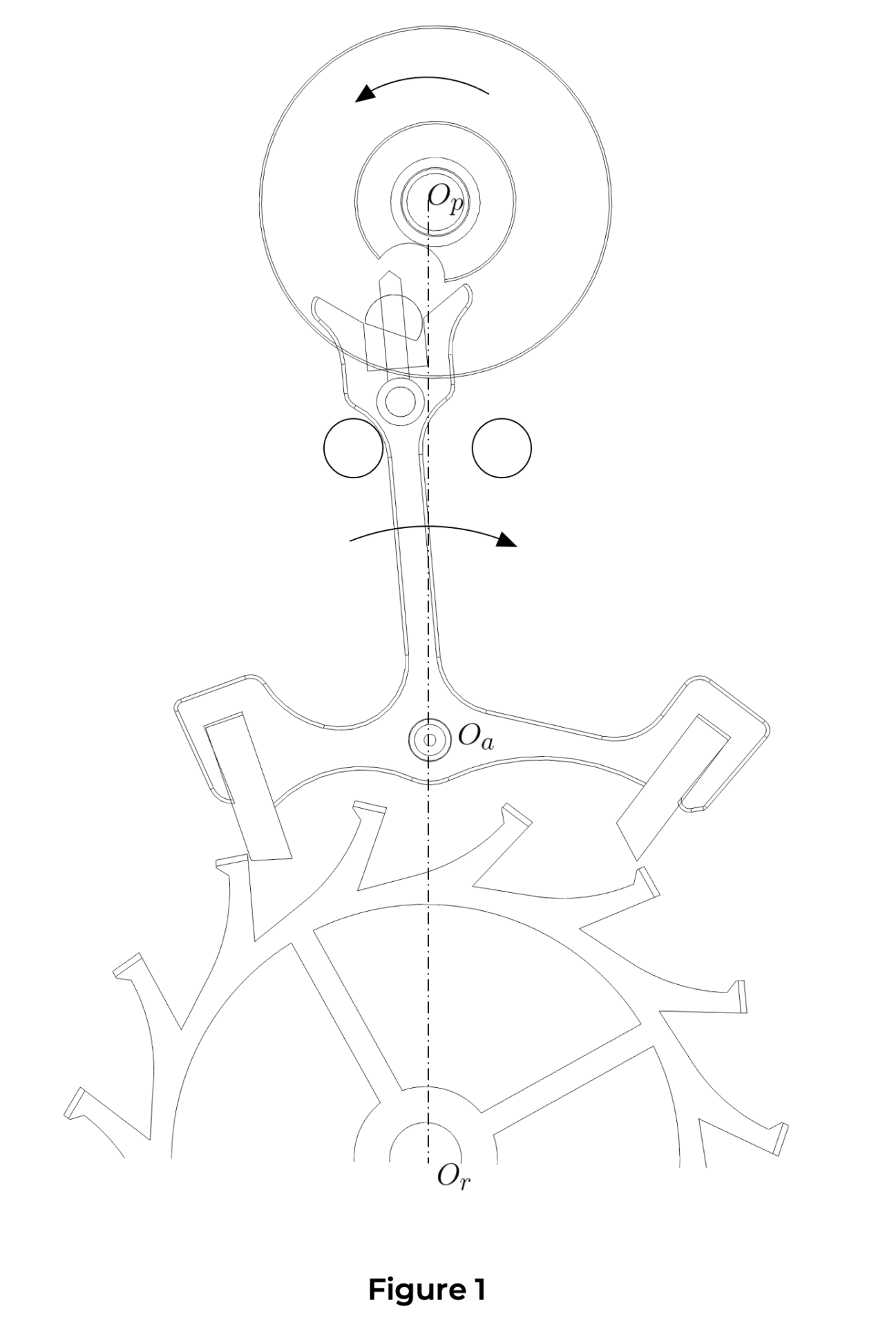
Figure 1: Operating speed 1:4

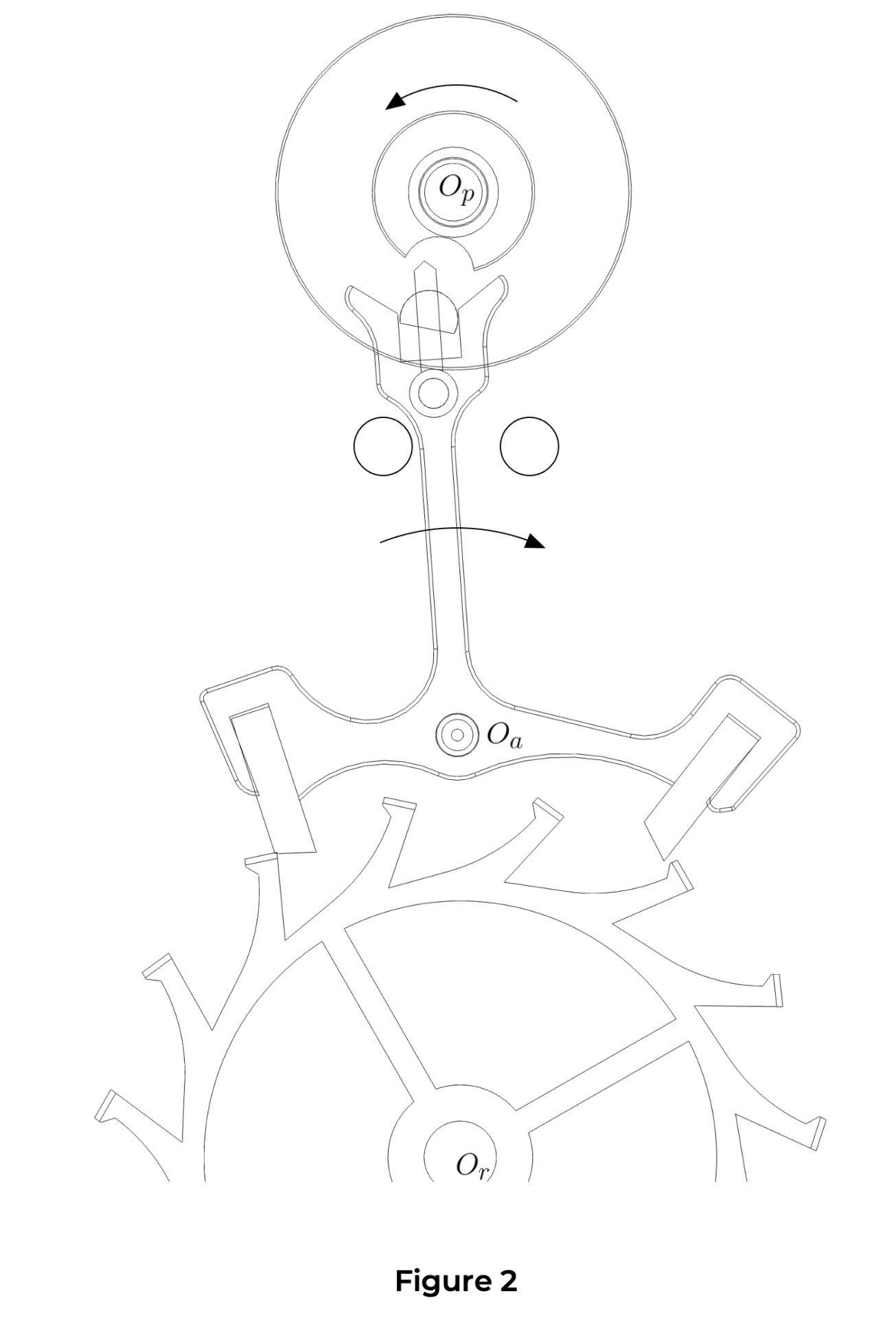
Figure 2: Real operating speed (21’600v/h)
- General description
- Functioning
- Definition of various angles
- Overbanking
- The shocks
- Analysis of rate diagrams
- The draw
- Stopping on the locking and impulse faces
The Swiss lever escapement is valued for its robustness, accuracy, and relative ease of manufacture. From the moment it appeared, this escapement quickly became the industry standard due to its technical merits and economic viability.
History
The Swiss lever escapement emerged in the second half of the 19th century as an improvement on the older, less efficient English lever escapement. Around 1842, Swiss watchmaker Georges-Auguste Leschot played a pivotal role in the industrialisation of this mechanism, enabling its widespread adoption. Over the decades, Swiss manufacturers refined the design, establishing it as a cornerstone of modern mechanical watchmaking.
Role of the escapement
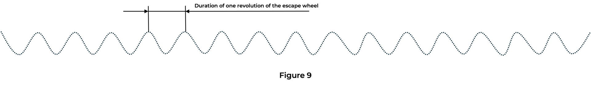
The escapement has two main functions. First, it must keep the gear train at a standstill, releasing it only periodically and at regular intervals. Without the escapement, all the energy stored in the barrel would be discharged within a few seconds, causing the gear train to spin uncontrollably. The escapement therefore locks the energy of the gear train and allows it to “escape” intermittently, hence its name. (As shown in Figure 1, the escape wheel advances in small jumps but remains stopped most of the time.)
The escapement also maintains the oscillations of the regulating organ by imparting a regular impulse to it. As the regulating organ is an oscillator, the escapement’s secondary role is to transform a linear motion (the rotation of the gear train) into an oscillatory motion (the oscillations of the balance wheel and hairspring) (Figures 1 & 2).
Escapement Type
The Swiss lever escapement belongs to the family of detached escapements, which means there is no continuous contact between the escapement and the oscillator, allowing the balance wheel to swing freely between impulses.
Component Overview
The Swiss lever escapement comprises the following elements:
-
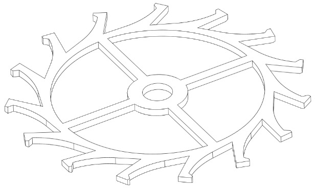
Escape Wheel: Typically made from steel, nickel-phosphorus (via UV-LIGA technology), or silicon (via DRIE).
-
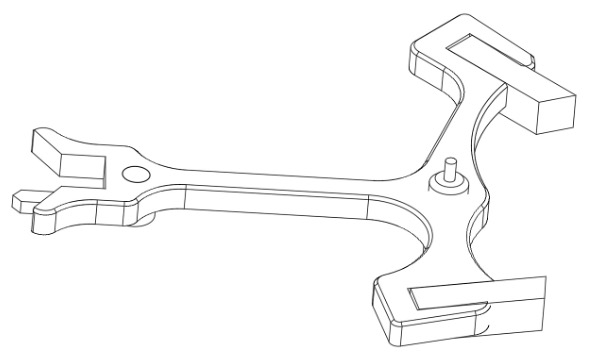
Lever: Usually constructed from steel with synthetic ruby pallets, though entire levers may also be produced in nickel-phosphorus (via UV-LIGA) or silicon (via DRIE).
-
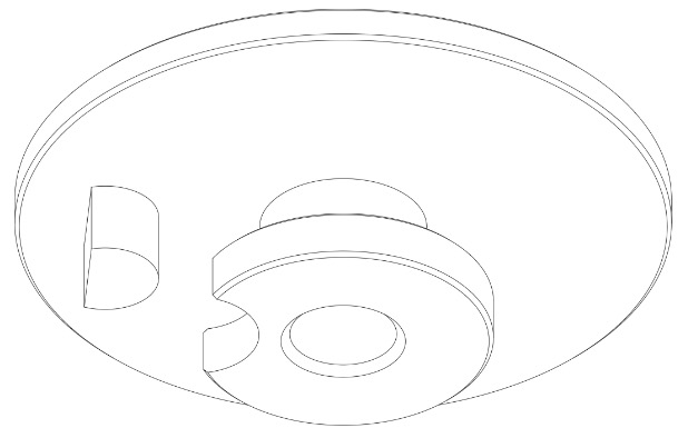
Roller: This consists of a large and a small roller (the safety roller), joined by a staff. It is generally made from ductile materials capable of withstanding impact (such as brass or CuBe alloys). Silicon is unsuitable for this purpose due to its brittleness. The impulse pin, typically made of synthetic ruby (corundum), is inserted or glued into the larger roller.
Advantages
-
Accuracy: The Swiss lever escapement is a mature and refined mechanism capable of achieving excellent chronometric performance.
-
Reliability: It performs well under shock and in varied positions, making it ideal for wristwatches.
-
Industrial Scalability: Regardless of the materials used in its components, the Swiss lever escapement can be mass-produced efficiently and cost-effectively.
-
After-Sales Servicing: Except for silicon versions, the Swiss lever escapement allows for conventional escapement adjusting, regardless of the watch’s age.
Drawbacks
-
Friction: Although materials such as steel and synthetic ruby, or silicon, are chosen to reduce friction, sliding friction between components remains significant. In particular, the steel teeth of the escape wheel interact with the ruby pallets of the lever via sliding contact. The Swiss lever escapement alone can consume approximately 30% of the mainspring’s nominal energy. Silicon variants now offer improved efficiency.
-
Maintenance: Traditional constructions (steel and ruby) require careful lubrication, which must be reapplied periodically to maintain optimal performance and minimise wear. Silicon-based escapements offer a solution here, as most can operate entirely without lubrication.
The operation of the Swiss lever escapement can be divided into four phases that invariably occur in the same cycle at each vibration of the regulating organ. These four phases are:
-
Locking
-
Unlocking
-
Impulse
-
Safety
Let us detail below the action of each component during each of these four phases.
1. Locking
During this phase, the entire going train is stopped, locked by the escapement.
Double roller
This is the only escapement component in motion at this time.
During the locking phase, the double roller freely performs its ascending supplementary arc α and then its descending supplementary arc β (Figure 1 below, point 1). This is the angle traveled by the double roller (and therefore the balance wheel) during the period when the escape wheel and lever are stopped.
Lever
The lever is stationary. The lever tail is held against the banking pin (Figure 1 below, point 2) by an escape wheel tooth under the effect of draw (see the “Draw” section).
Escape wheel
Like the lever, the wheel is stationary. One of its teeth rests on the locking face of a pallet of the lever (Figure 1 below, point 3).
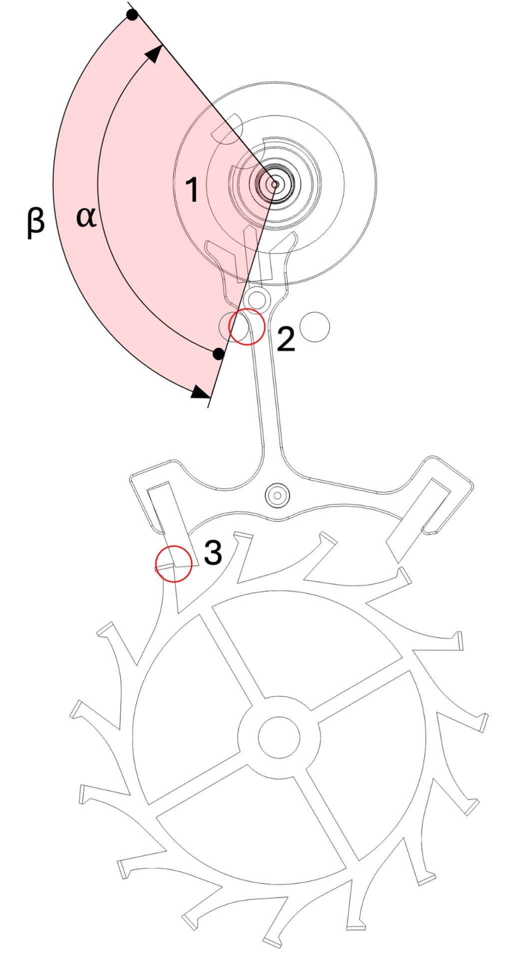
Figure 1
locking
2. Unlocking
During this phase, the escape wheel and the going train move slightly backward.
Double roller
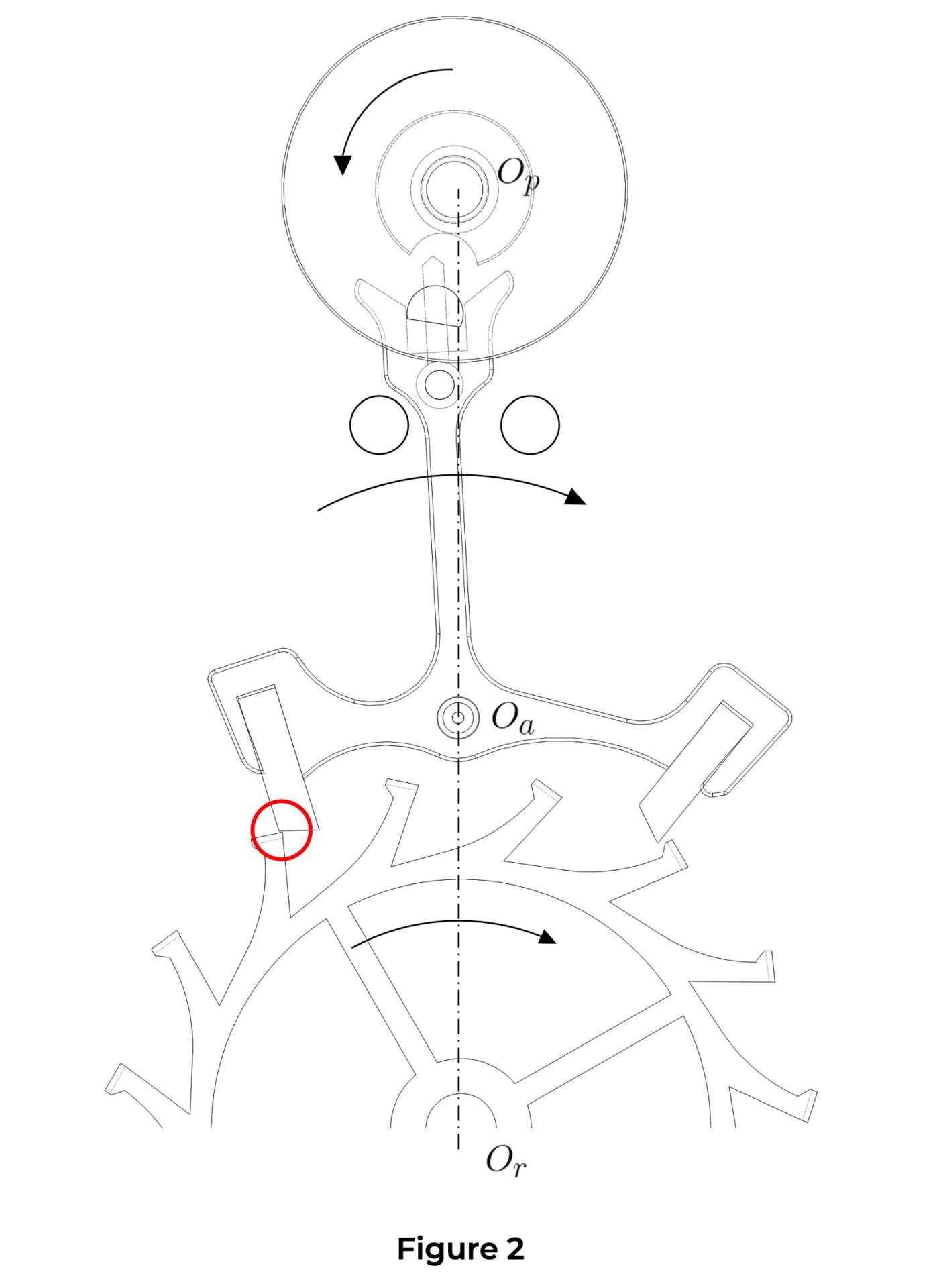
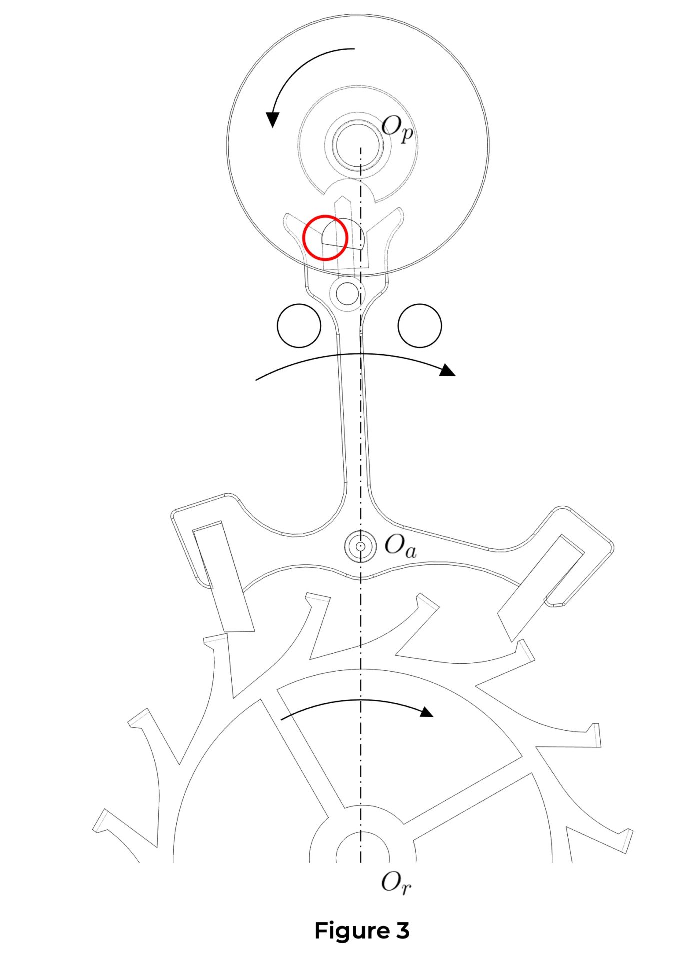
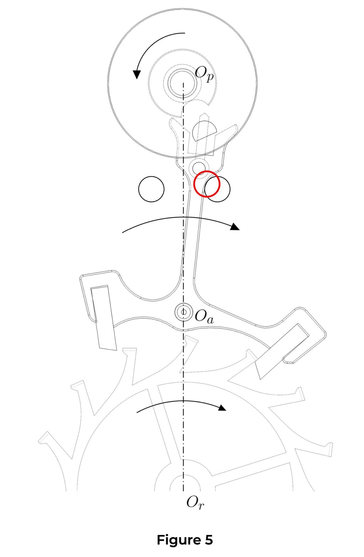
The unlocking phase begins when the roller jewel comes into contact with the fork (Figure 2, point 4). The unlocking phase of the double roller corresponds to the angle α it travels while the roller jewel pushes the lever fork (Figure 3).
Lever
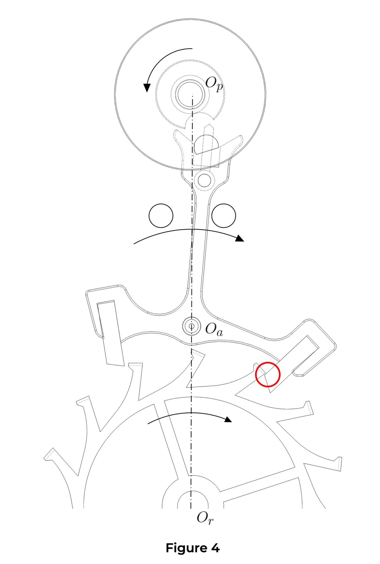
The unlocking phase of the lever corresponds to the angle β it travels while an escape wheel tooth acts on the pallet’s locking face (Figure 3). The unlocking phase ends when the wheel tooth theoretically reaches the pallet’s locking point (Figure 4, point 5).
Escape wheel
Through the lever action and the escapement geometry, the escape wheel moves slightly backward during the unlocking phase (geometric recoil, approx. 0.15–0.25°), then continues its motion while briefly detaching from the pallet’s locking face (dynamic recoil, approx. 0.04°). The sum of geometric and dynamic recoil forms angle γ (Figure 3).
Finally, the escape wheel resumes its normal direction of rotation under the driving force. As with the lever, the unlocking phase is considered to end when the wheel tooth is theoretically at the pallet’s locking point (Figure 4, point 5).
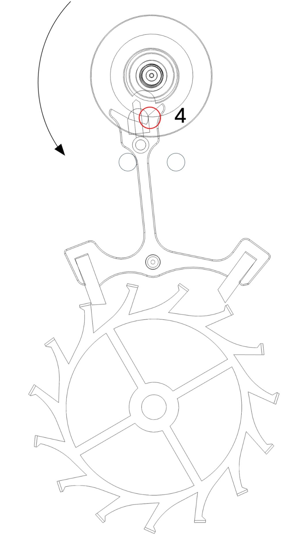
Figure 2
start of unlocking
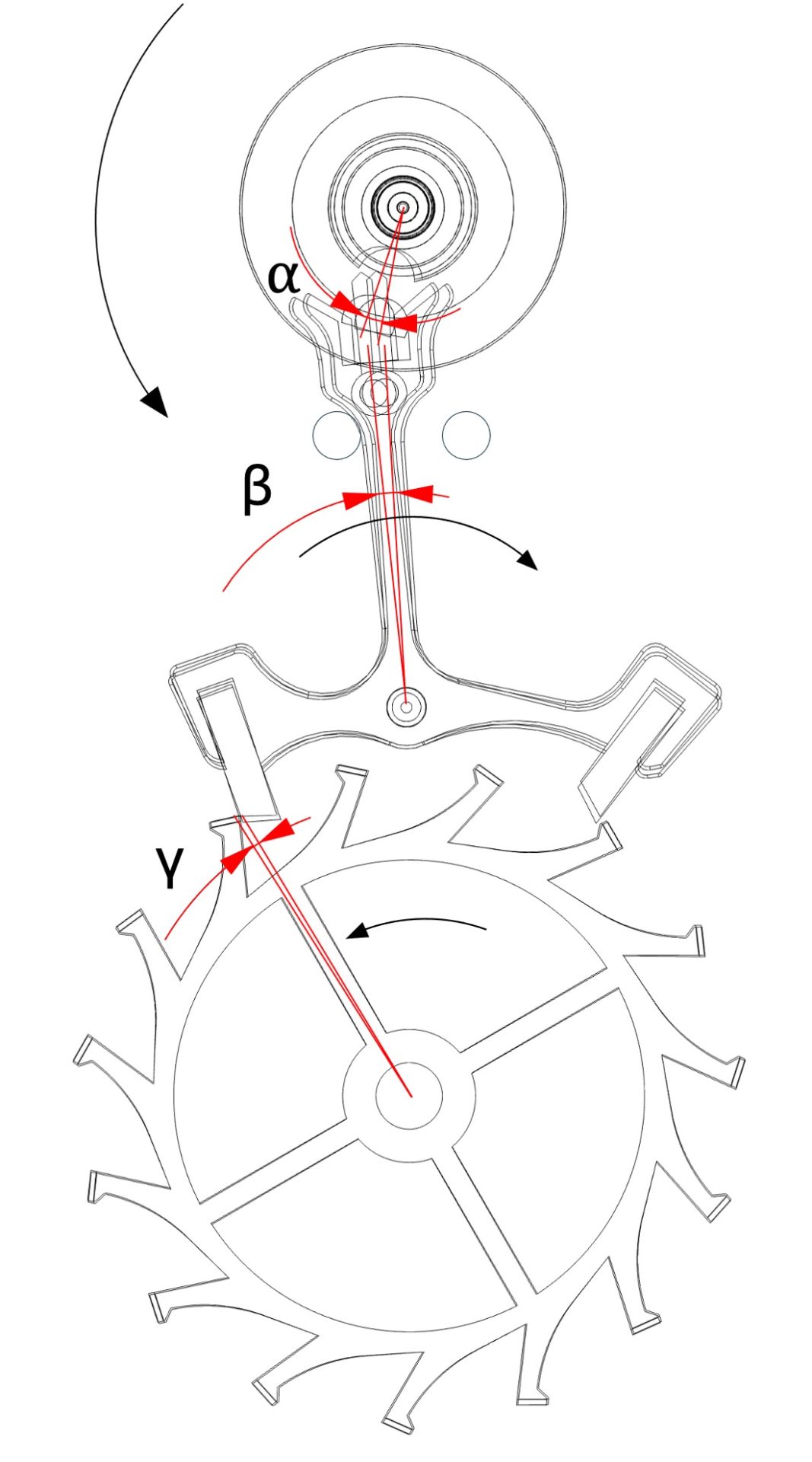
Figure 3
unlocking phase
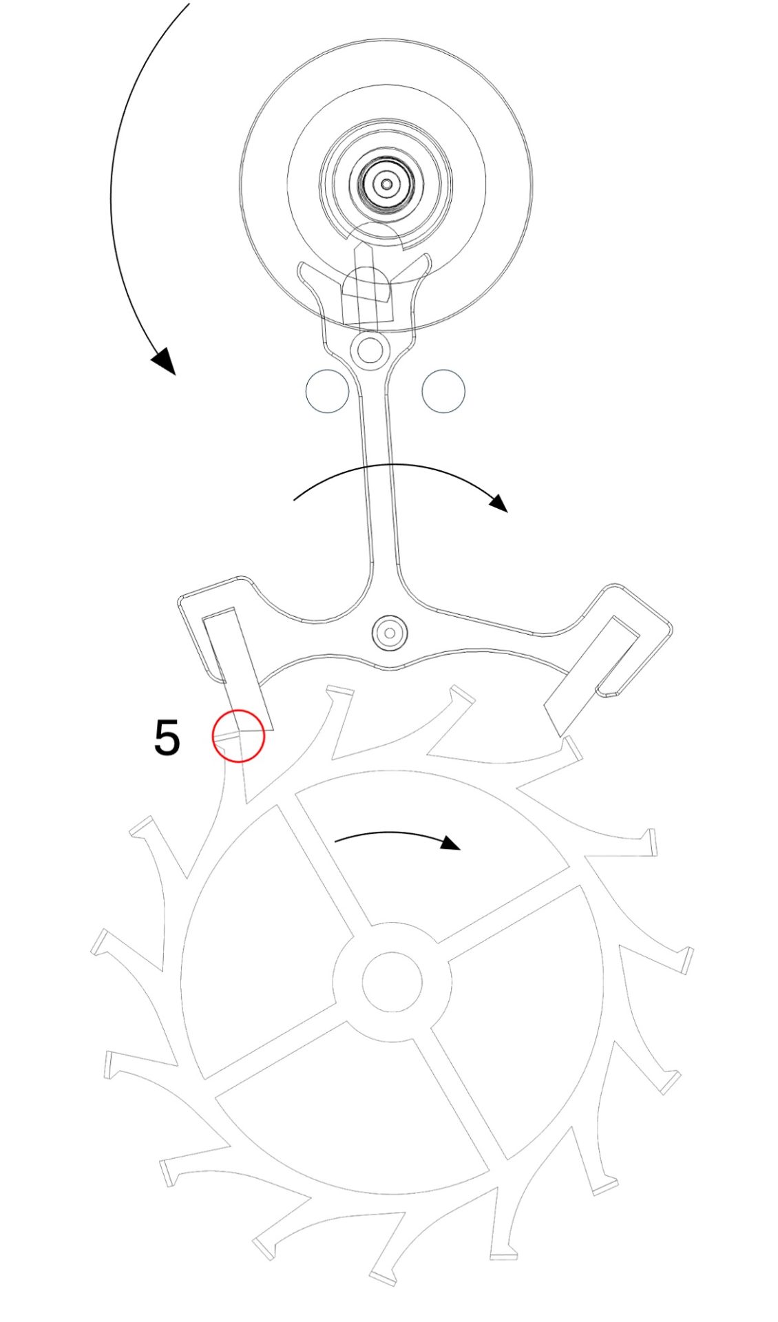
Figure 4
end of unlocking
4. Safety
The safety phases are angles traveled by the escape wheel and the lever in pure loss just after the impulse phase.
Double roller
At the start of the safety phase, the impulse pin loses contact with the lever fork (Figure 9, point 9). The double roller then freely begins its ascending supplementary arc α’ followed by its descending supplementary arc β’ (Figure 9).
Lever
The lever’s safety angle is called run to the banking. This is the angle traveled by the lever tail from the moment an escape wheel tooth comes into contact with the pallet’s locking face (Figure 10, point 11) to the moment the lever tail comes into contact with the banking pin under the effect of draw (Figure 11, point 12).
Escape wheel
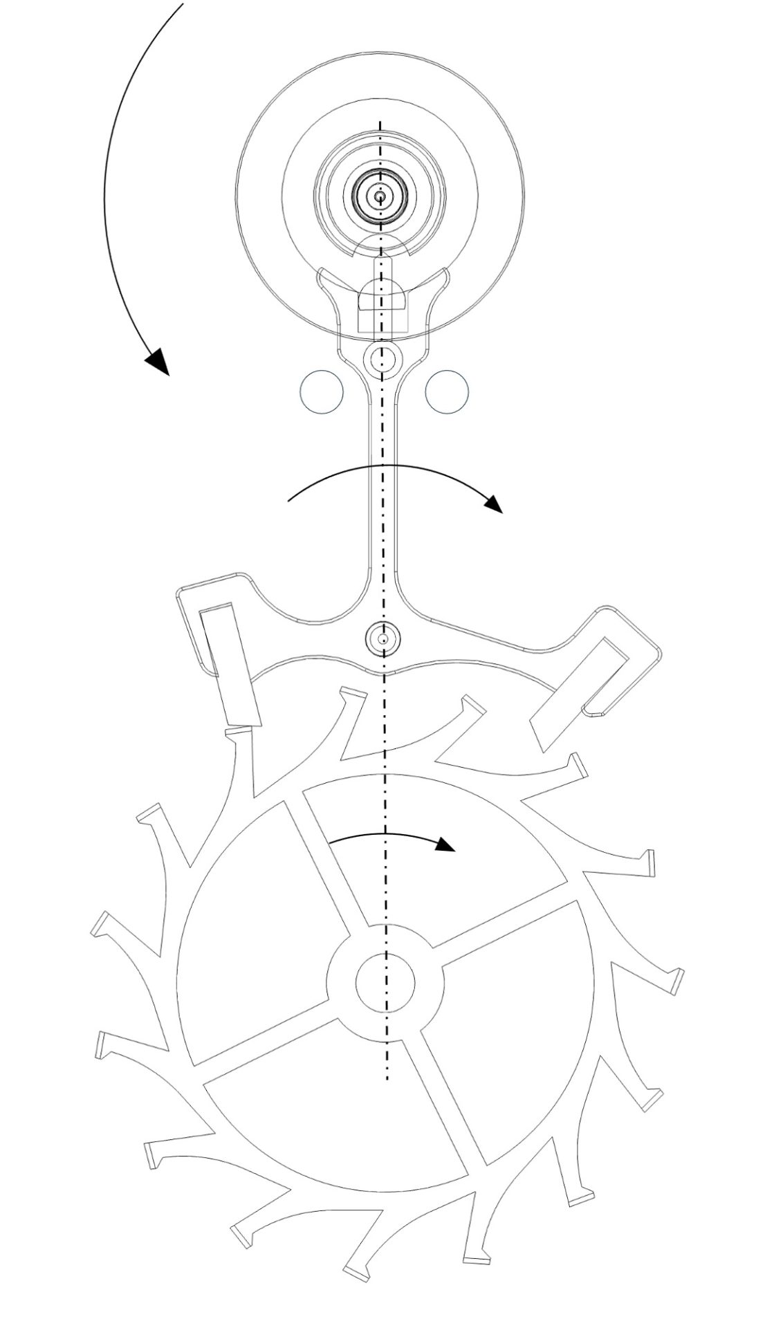
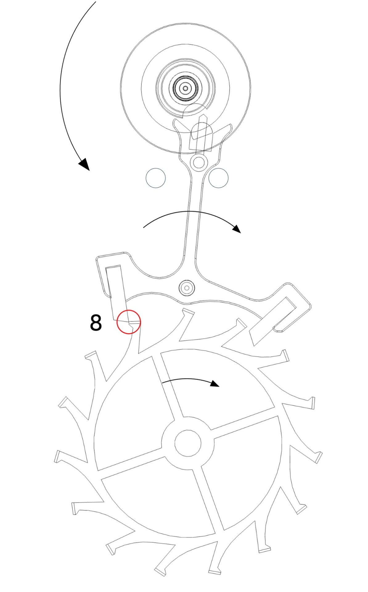
The safety angle of the escape wheel is called the drop. The drop corresponds to the angle traveled by the wheel from the moment one of its teeth leaves the pallet’s impulse face (Figure 9, point 10) until another tooth comes into contact with the locking face of the opposite pallet (Figure 10, point 11).
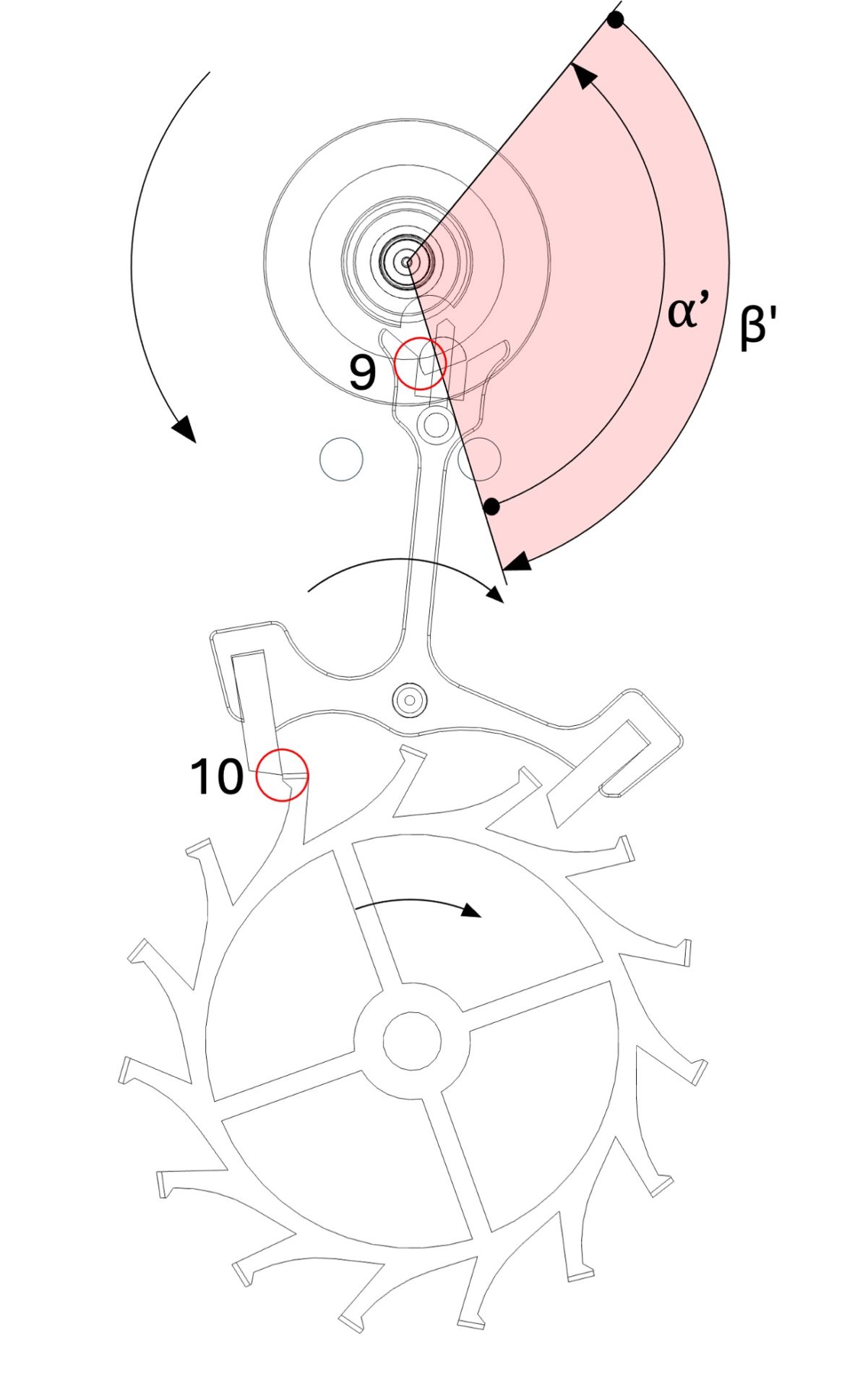
Figure 9
start of the drop (safety)
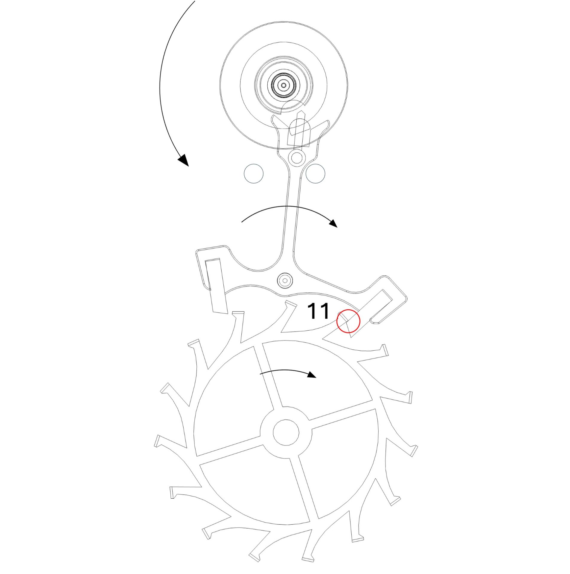
Figure 10
end of the drop and start of run to the banking (safety)
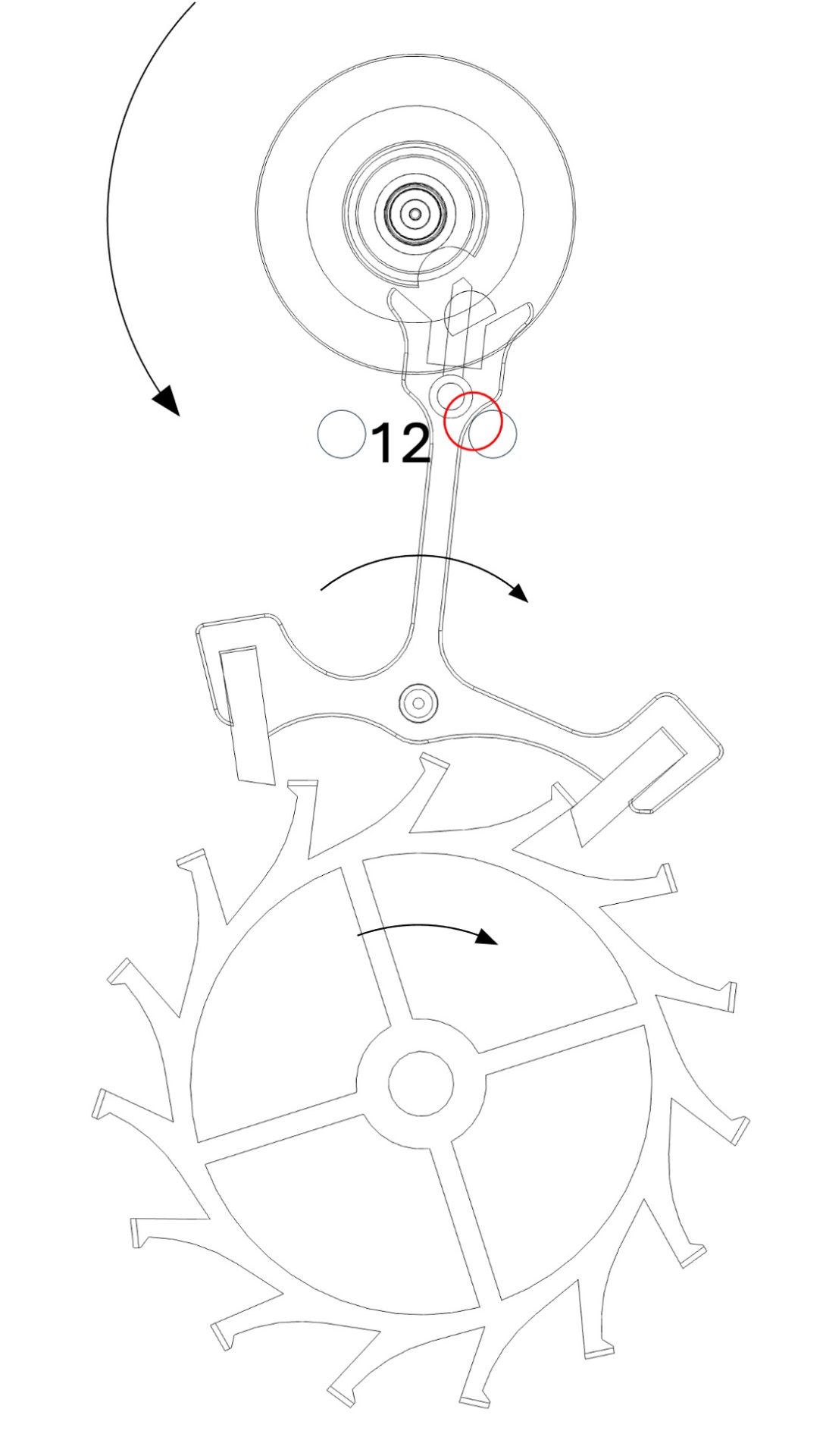
Figure 11
end of run to the banking (safety)
Note:
For a complete understanding of the operation of the swiss lever escapement, please refer to the two animations shown at the top of this page.
1. The Roller (de facto the balance-wheel)
Description of the different angles of the roller (and therefore of the balance-wheel) during two alternations (one oscillation).7


(*) Important:
When the escape wheel performs its dynamic recoil (see the Functioning tab), the lever continues its motion while being driven by the impulse pin of the roller. When the escape wheel resumes its forward motion, the tooth of the wheel comes back into contact with the impulse face of the pallet on the lever and the impulse phase transmitted to the balance-wheel begins. During this period, the contact between the impulse pin and the lever pallet is briefly interrupted, and the roller (and therefore the balance) moves freely through a small angle between the end of unlocking and the start of the impulse (angles described above as the balance-wheel’s free motion).
2. The Lever
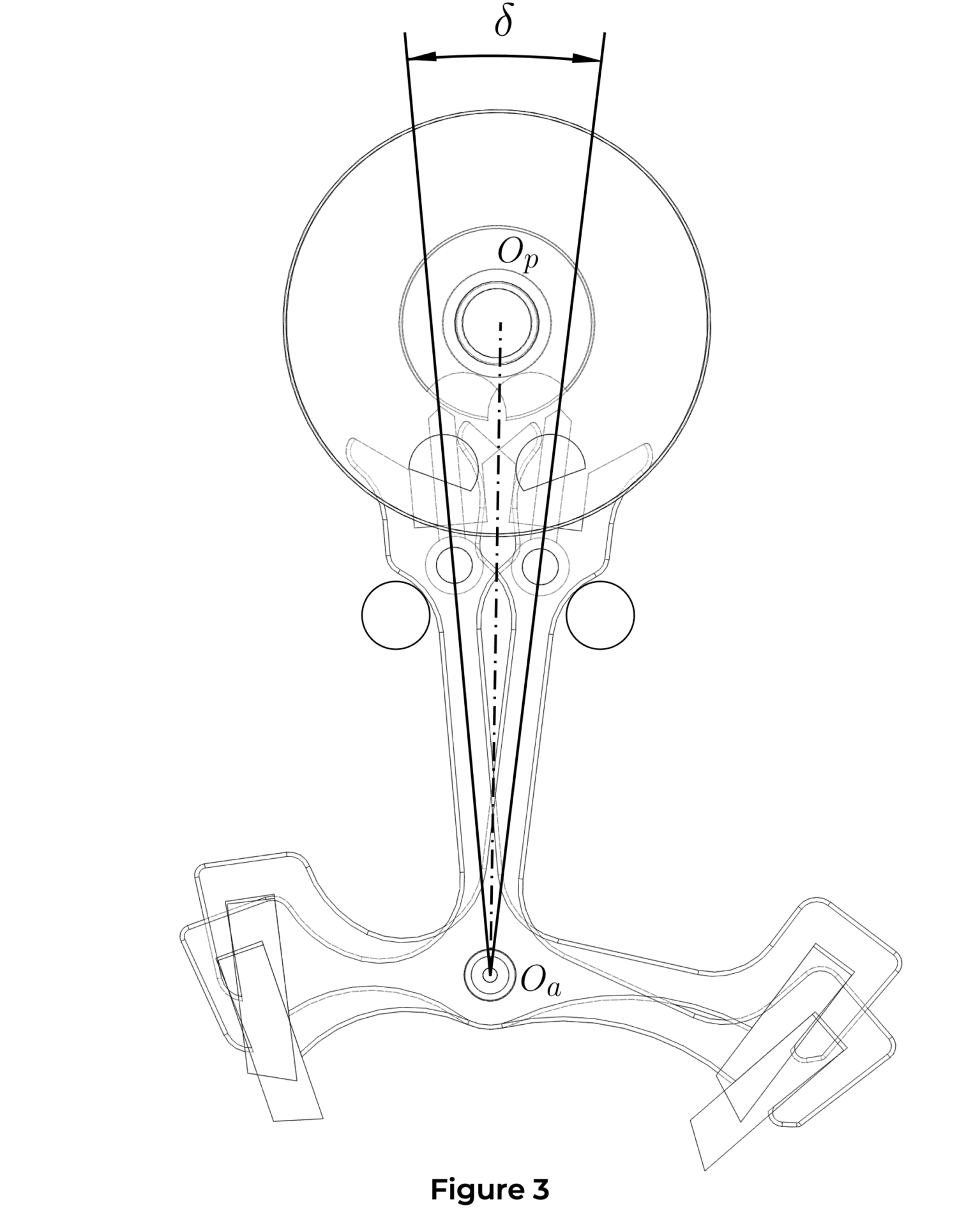
2.1 Total Lift Angle ![]() (Figure 3)
(Figure 3)
The total lift angle of the lever corresponds to the displacement of the lever between the two banking pins (or banking blocks). It corresponds to the sum of the unlocking angles, the impulse angles, and the run to the banking, and its value generally lies between 12° and 20°.
2.2 Virtual Locking Angle ![]() (Figure 4)
(Figure 4)
This is the angle between the locking face (resting tip) of the pallet (see Lever) and the point at which the tooth of the escape wheel lands on the locking face of the lever pallet.
2.3 Run to the banking Angle ![]() (Figure 4)
(Figure 4)
This is the angle through which the lever travels between the end of the impulse and the moment when the lever bears against the banking pin (or banking block) (see Functioning tab).

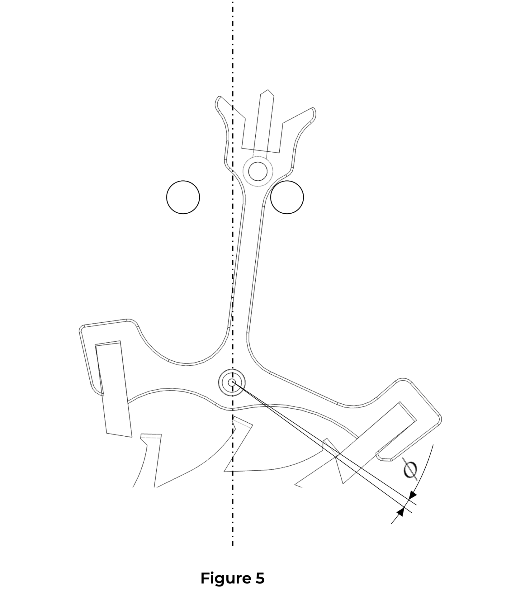
2.4 Total Locking Angle ![]() (Figure 5)
(Figure 5)
The total locking angle corresponds to the sum of the virtual locking angle (Figure 4 – ![]() ) and the lost motion angle (Figure 4 –
) and the lost motion angle (Figure 4 – ![]() ).
).
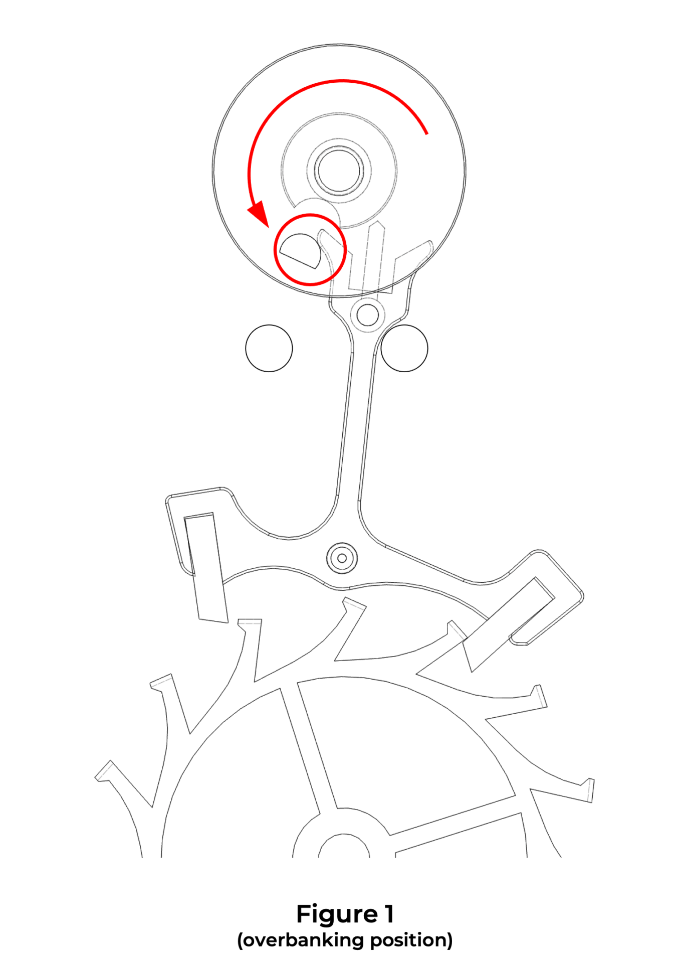
While the balance-wheel travels its additional arc (ascending or descending), the lever rests against one or the other of the banking pins (or banking blocks) under the effect of draw (see Draw tab). If a shock overcomes the draw torque, the lever tips against the opposite banking pin. At the end of the balance-wheel’s descending additional arc, the impulse pin of the roller then strikes the back of the horn, thereby causing the watch to stop immediately (Figure 1).
To prevent overbanking, the Swiss lever escapement has four components:
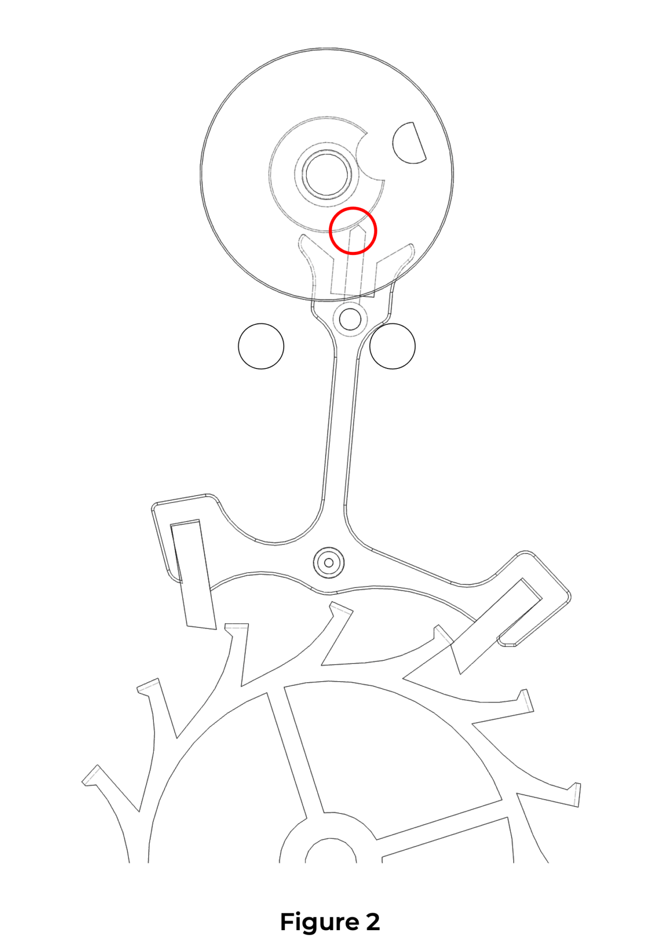
When the balance wheel travels through its supplementary arc, the guard pin rests against the edge of the safety roller, preventing the lever from tilting against the other banking pin and thus preventing overbanking (Figure 2).
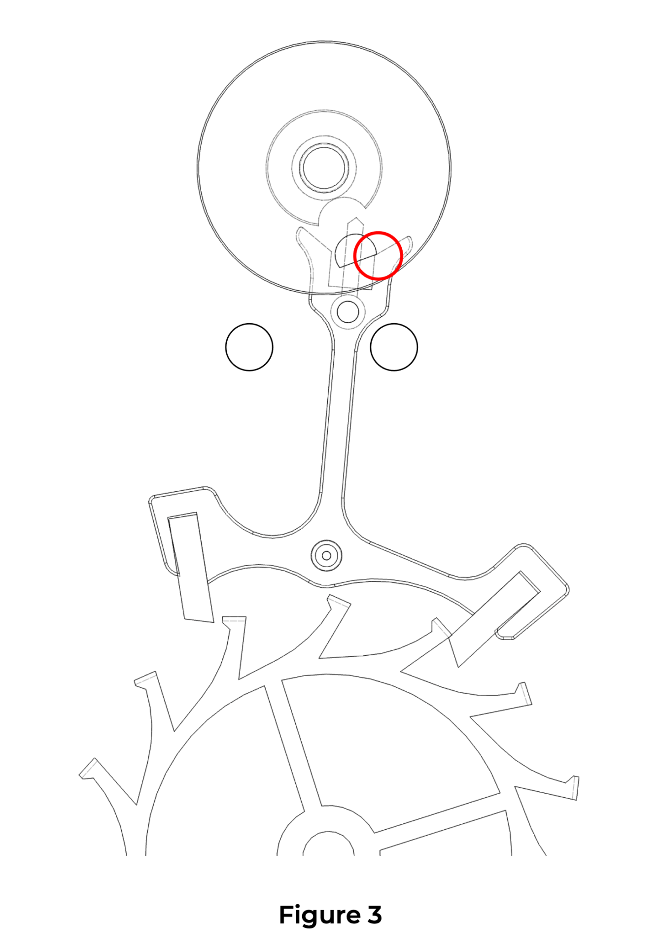
The safety roller features a notch aligned with the impulse pin. During the unlocking and impulse phases (see the functioning tab), this notch allows the guard pin to pass through and the lever to tilt normally from one banking pin to the other. During these phases, it is the inside of the horns that comes into contact with the impulse pin, thus preventing overbanking (Figure 3).
The various impacts of the Swiss lever escapement are audible to the ear. This is the “tick-tock” of mechanical watches. But when the human ear perceives a tick or a tock, the escapement has actually emitted five sounds resulting from five impacts. These sounds are so close together that the ear hears only one (a tick or a tock).
Analyzing these sounds, by the intensity of each and the spacing between them, allows for the detection of malfunctions or incorrect adjustments of the escapement. Likewise, the graphs from a timing machine can help identify problems related to the escapement. For each alternance (vibration), these five impacts are as follows:
- Unlocking
- Start of the escape wheel impulse
- Start of the balance wheel impulse
- End of the drop
- End of run to the banking
1. Unlocking
The first impact of an alternance (vibration) occurs when the impulse pin comes into contact with the inside of the lever fork (Figure 1).
2. Start of the escape wheel impulse
Shortly after unlocking, the escape wheel tooth drops onto the impulse plane of the pallet. This is the second impact (Figure 2).
3. Start of the balance wheel impulse
The fork catches the impulse pin and transmits its impulse to the balance-wheel via the roller. This is the third impact (Figure 3).
4. End of the drop
A tooth of the escape wheel comes into contact with the locking face of a pallet of the lever (Figure 4).
Watch rate testing instruments provide a wealth of information such as the instantaneous daily rate, amplitude, and beat error. However, a proper reading of the diagrams produced by timegraphers also makes it possible to identify numerous issues arising from the gear train, the escapement, and the regulating organ.
Thus, when a perfectly adjusted watch is running without faults, the diagram displays a single horizontal line (Figure 1).
 When the beat error is too large, two parallel lines appear on the diagram (Figure 2). The correction consists of adjusting the beat error (via the movable stud holder or the collet) and then readjusting the rate.


Draw is a safety feature that keeps the lever tail pressed against the banking pins when the balance wheel performs its supplementary arc. This prevents the guard pin from coming into contact with the edge of the safety roller and disturbing the period of the regulating organ.
The mechanical action of draw results from the pressure of an escape wheel tooth on the locking face of one or the other pallet of the lever.
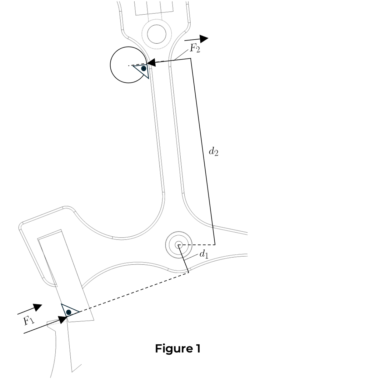
Thus, the force F1 exerted by the wheel tooth acts perpendicularly to the locking face of the pallet and creates a torque via the lever arm distance d1 relative to the lever’s pivot point. This torque causes the lever tail to be pressed against the banking pin with a force F2 and lever arm d2, corresponding to the distance between the lever’s pivot point and the center of the banking pin (Figure 1).
The lever is thus kept pressed against the banking pin. If a shock manages to overcome the draw force, the lever will move and the guard pin may briefly come into contact with the edge of the safety roller, but the draw force will immediately return it to its resting position.
Value of the draw torque
The draw torque can be defined by the following calculations:

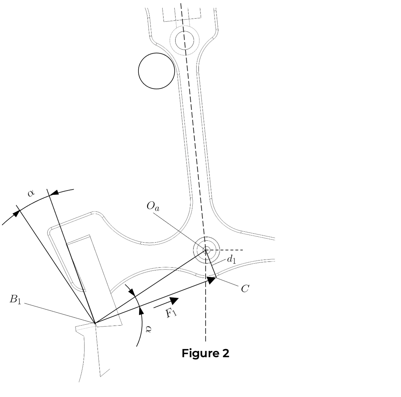
The distance d1 varies according to the value of angle α measured at the locking point B1. A variation in angle α therefore causes an increase or a decrease in the draw torque M (Figure 2).
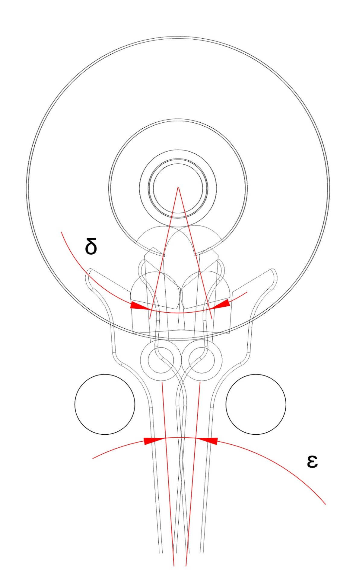
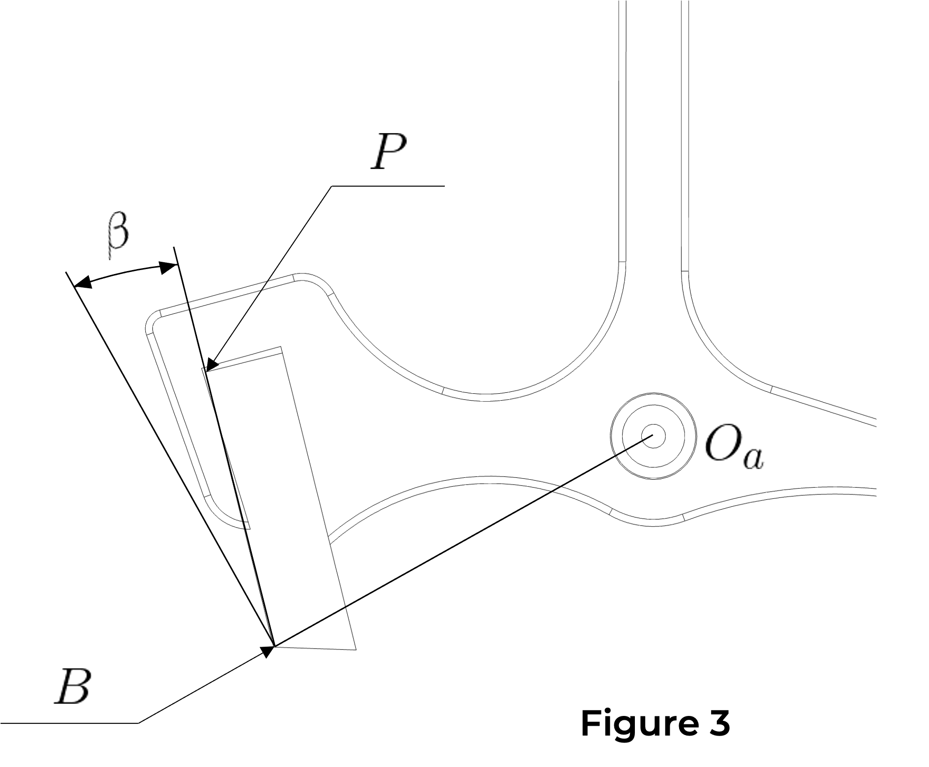
The draw angle β is the angle between a perpendicular drawn at the locking point B to the line connecting this point to the lever’s pivot point and the pallet’s locking face BP (Figure 3).
As we have just seen, the draw angle β is defined at the pallet’s locking point B. It can also be defined at the pallet’s locking point B1. In that case, the draw angle is referred to as α (Figure 4). It is thus understood that during unlocking (see “functioning” section), the draw angle varies from β to α.

The draw angle is defined during the construction of the escapement (ideally about 9° for a steel wheel–ruby pallet combination). However, a draw angle that is too small reduces the draw force and therefore its safety. It also increases the coefficient of friction. Conversely, an angle that is too large increases the torque required for unlocking and increases the amount of escape wheel recoil (loss of impulse value). Thus, a draw angle that is too small or too large disturbs the timekeeping qualities of the regulating organ. For a steel escape wheel and ruby pallets, an ideal draw angle is generally considered to lie within a range of about 13° to 16°.
Finally, note that during unlocking, the draw angle increases on the entry pallet by the value of angle ε (β = α + ε) (Figure 4), whereas it decreases on the exit pallet by the same value ε (β = α − ε) (Figure 5).

1. Stopping on the locking face
Stopping on the locking face is observed when the movement is fully wound. The balance wheel is then positioned manually so that the impulse pin of the roller is at the beginning of the unlocking phase (see “functioning” section) (Figure 1).
If the balance wheel cannot unlock the escape wheel from the pallet’s locking face by the hairspring’s force alone, the movement is considered to have stopping on the locking face.
Stopping on the locking face is most pronounced when the movement is fully wound, because the force exerted by the escape wheel tooth on the pallet’s locking face (and thus the draw) is then at its maximum. As described in the “Draw” section, draw increases during unlocking on the entry pallet and decreases during unlocking on the exit pallet.
Movements with a diameter greater than 24 mm must not exhibit stopping on the locking face under any circumstances. However, for movements with a diameter under 24 mm, it is not always possible to avoid it. Indeed, as the movement size decreases, the moment of inertia and the hairspring torque decrease more rapidly than the mainspring torque.
In movements under 24 mm in diameter, stopping on the locking face is not tolerated after 24 hours of running, as the difficulty in unlocking significantly disturbs the isochronism of the regulating organ.
1a. Causes of stopping on the locking face
Possible causes include:
-
Insufficient freedom or poor lubrication of the escapement components (noticeable through low amplitude)
-
Defective surface condition of one or both pallet locking faces, or poor lubrication between escape wheel and pallets
-
Defective profile or surface condition of the escape wheel teeth locking faces
-
Excessive draw angle
-
Insufficient shake of the impulse pin of the roller in the lever fork
-
Fork entrance horns that are too short, leading to excessive guard-pin shake at the start of the balance wheel’s supplementary arc
-
Incorrect beat setting (out of beat)
How to prevent or limit stopping on the locking face
To prevent or limit stopping on the locking face (depending on the movement diameter), the balance wheel position at which locking occurs must be determined. It is then possible to reduce the total pallet engagement to angularly shift the end of unlocking so that it occurs before the locking position. However, this solution reduces the value of the run to the banking.
Another, more complex solution is to increase the inclination of the pallets’ impulse faces. This reduces total engagement without reducing the run to the banking angle. Care must be taken to maintain sufficient virtual engagement.
During the development of small-diameter movements, stopping on the locking face can be minimized by increasing the ratio between the lever lift angle and the balance lift angle (see table below). This involves reducing the roller diameters and lengthening the lever fork. The balance wheel then begins unlocking at a greater angle from the dead point, increasing its torque and limiting stopping on the locking face. However, a large balance wheel lift angle increases the escapement’s disturbing influence on isochronism.
2. Stopping on the impulse face
Stopping on the impulse face is observed by winding the mainspring by two ratchet teeth. The balance wheel is then positioned manually so that one escape wheel tooth is at the start of the pallet’s impulse face (Figure 2). If the impulse is not fully delivered with this small driving force, the movement is considered to have stopping on the impulse face.
All movements exhibit stopping on the impulse face. To check whether it is acceptable, the mainspring is wound very gradually until the movement starts running spontaneously, while carefully observing the rotation of the ratchet wheel. The accepted values for overcoming stopping on the impulse face are as follows:
-
Small-diameter movements: start-up after 4 to 5 ratchet teeth of winding
-
Medium-diameter movements: start-up after 1/2 turn of ratchet winding
-
Large-diameter movements: start-up after 1 to 2 full turns of ratchet winding
2a. Causes of locking on the impulse face
Possible causes include:
-
Insufficient driving force (mainspring too weak, lack of freedom in the gear train, gearing defects, poor lubrication)
-
Insufficient freedom of the lever or the balance wheel
-
Defective surface condition or profile of the pallet impulse face
-
Defective surface condition or profile of the escape wheel teeth impulse faces
-
Poor lubrication between escape wheel and lever
-
Insufficient shake of the impulse pin in the lever fork
-
Defective surface condition or profile of the lever fork entrance
-
Incorrect beat setting (out of beat)
Important
Stopping on the impulse face increases with movement diameter. It is not truly a defect, as it does not harm the accuracy of the movement or the isochronism of the regulating organ. However, if it is excessive, the movement will not start spontaneously under the sole influence of the driving force and will require a manual initial impulse to the balance wheel (for example, by quickly rotating the movement or the watch).
To achieve the best possible adjustment and isochronism, it is preferable to have the smallest possible balance lift angle.
Accepted values & lift-angle ratios
