
MENU
1. Introduction
This is a machine for cutting the profile (contour) of components. The principle of an Electrical discharge machining (EDM) machine consists of machining the material by generating a series of sparks.
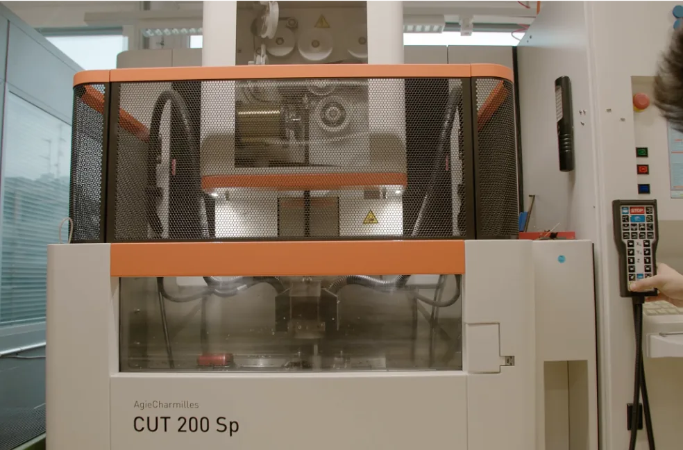
Figure 1
Electrical discharge machining (EDM) machine
Click on the thumbnail to enlarge it
2. History
The invention of the method for processing metals by electric spark (electrical erosion) was presented in 1943 by the Soviet scientist couple Natalya and Boris Lazarenko. The technology quickly found its industrial applications, and Switzerland has been producing and exporting its machines since 1952. The arrival of computing and numerical control in the eighties gave this technology a still remarkable boost.
3. Description of the machine
The machine consists of a large tank in which all machining operations take place. This tank has a front door allowing material to be loaded and the machine to be set up. At the bottom of the tank is a table to which the material trays (raw material blanks) are fixed. The table is motorized and can move longitudinally and laterally (X and Y axes), sometimes also along rotation axes (A and B). A pre-drilled hole passes through the raw material outside the outline of the component to be cut. The tray is positioned and firmly fixed to the machine table. Depending on the nature of the Material, the thickness of the trays and the complexity of the component’s profile, several trays can be stacked on the machine table and, during the same operation, as many components can be cut as there are stacked trays. Directly above the tank, the machine has two large wire spools, similar to the magnetic tape of a tape recorder. One contains the new wire, the other receives the used wire. The wire is made of Brass or copper laminate, and its diameter can vary from 0.02 to 0.3 mm depending on the machine’s capacity and the component to be cut. A roller system guides the wire and maintains ideal tension. As it exits the machine, the wire is guided vertically by the operator through the hole previously made in the tray. It is then guided towards the outside of the tank and rises vertically to reach the recovery spool. Once the component’s outline has been recorded in the machine’s computer system, the operator can close the front door. Before the machine begins machining the component, the first step is to fill the tank with a dielectric solution (water or mineral oil). A dielectric has the property of weakly conducting electric current, but freely allows electrostatic forces to act.
4. Operating principle
The tray is immersed and traversed by the wire constituting the system’s electrode. During machining, the wire continuously unwinds from one spool to the other. The machine sends short pulses of electric current to the wire. By precisely adjusting the current intensity, a spark occurs at each pulse, causing an arc between the wire and the workpiece (the inner wall of the hole made in the tray). The Temperature generated by the succession of sparks can reach 8,000 to 12,000 °C. At each pulse, the material locally transforms into plasma, which is expelled by the dielectric fluid, thus leaving a crater behind. The succession of craters creates the cutting of the component. Throughout the process, the machine’s table and the tray move simultaneously along the Y and Z axes in order to faithfully and precisely trace the component’s contour (the wire’s position is fixed). Some machines allow the table to be tilted, which makes it possible to cut inclined planes.
5. Advantages and disadvantages
Wire electrical discharge machining (EDM) offers many advantages over traditional machining technologies. The very small diameter of the wire is up to ten times smaller than that of the smallest milling cutters. This allows the wire to cut much more complex contours with increased precision. In addition, there is never any contact, and therefore no mechanical stress, between the tool (the wire) and the component. This makes it possible, for example, to manufacture long and thin components, such as springs, without risking breaking them, as would be the case on a milling machine or machining center. By stacking the trays, the number of components manufactured during the same cycle can be increased. However, this number is limited and the machine’s feed rate is not very high (0.2 to 10 mm/min). As a result, when technically possible, Stamping is preferred over electrical discharge machining (EDM) when it comes to producing components in large series. Finally, only materials that conduct electricity are logically eligible for this technology.
6. Examples of components produced by electrical discharge machining (EDM)
As soon as the Material is conductive, the list of applications is virtually endless. From the Case middle of Case to the smallest and finest springs of a Movement, the advantages of the technology often justify the choice of Electrical discharge machining (EDM). EDM is also widely used to produce the dies and punches for stamping tools. This technology has considerably reduced the manufacturing costs of stamping tools, which were previously entirely shaped mechanically from the Mass. Finally, it is particularly valued for manufacturing small, fine components with complex profiles, as well as for small production runs and prototyping, since it does not require the manufacture of specific tooling, as is the case with milling or stamping operations.
This page has been automatically translated from the reference French version using an artificial intelligence tool. Errors or inaccuracies may remain. If you notice any, especially if this is your native language, please feel free to report them to info@horopedia.org. Your input helps us improve the quality of the encyclopedia.
While awaiting translation, images and videos remain temporarily displayed in French.
Thank you for your understanding.