
MENU
1. The chronograph: definition and position within complications
The chronograph is a horological complication allowing the measurement of short time intervals, independently of the time display. Its purpose is exclusively metrological: it measures a duration, starts and stops on command, and can be reset.
The term “chronograph” is formed from the Greek χρόνος (chronos, time) and γράφειν (graphein, to trace). The name evokes the historical origin of the instrument: the first chronographs, in the 19th century, deposited a trace of ink on a dial to record the measured instant. The inking hand marked the start and stop instants with a visible line.
The complication appeared in the form of a pocket watch during the first half of the 19th century. The wrist chronograph developed from the early 20th century onward, to meet the needs of the military, navigators, doctors and pilots. It is today one of the most widespread mechanical complications in watchmaking.
The two-pusher chronograph is the standard and most widespread form of the modern mechanical chronograph. It is distinguished from the single-pusher chronograph by the functional separation between the start/stop pusher and the reset pusher. This architecture gives the user total and intuitive control over the three measurement operations.
2. The three-time principle
The term “three-time” designates the fundamental operating sequence of the chronograph. This sequence comprises three distinct and successive actions: start, stop and reset. Each of these actions corresponds to a different mechanical position of the chronograph’s control organs.
The first action, start, engages the drive of the chronograph wheel by the base train of the watch. At this moment, the central chronograph hand begins rotating and the counters move simultaneously. The chronograph train is thus connected to the movement’s energy source.
The second action, stop, interrupts this drive. The chronograph wheel is halted at the position reached. The chronograph hand stops, retaining the measured value. The base train continues to operate normally for indicating the time. The chronograph can be restarted from this position, resuming the measurement without losing the previous interval.
The third action, reset to zero, is only possible when the chronograph is stopped. It instantly returns all the chronograph hands and all counters to the zero position, through the action of the hammers on the reset-to-zero hearts. The mechanism is then ready for a new measurement.
3. The two pushers and their role
The two-pusher chronograph has two independent control mechanisms usually located in the case middle, on either side of the crown. The first pusher is usually positioned at 2 o’clock, the second at 4 o’clock. Positions at 8 and 10 o’clock also exist depending on the movement’s architecture and the manufacturer’s aesthetic choices.
The first pusher alternately controls start and stop. Each press toggles the mechanism from one state to the other. When the chronograph is stopped, a press starts it; when it is running, a press stops it. This toggle logic corresponds to a mechanical permutation controlled by the column wheel or the shuttle (control cam).
The second pusher exclusively controls the reset. It is mechanically inactive when the chronograph is running.
The separation of functions between the two pushers constitutes the major functional advantage of the two-pusher chronograph over the single-pusher version. It allows for accumulating different measurements and stopping the chronograph, reading the measured value, then deliberately resetting it to zero, without risk of accidental reset caused by an awkward double press.
4. The column wheel
4.1 Architecture and operation
The column wheel is the most characteristic sequencing component of high-quality chronographs. It defines the active positions of the control levers according to a precise mechanical program. Its shape is recognizable: a series of equidistant vertical columns alternate with notches around its upper periphery.
Each time the start/stop pusher is pressed, the column wheel advances one step. It is driven by a beak or a click actuated by the pusher. The alternation of columns and notches determines the high or low position of the control levers resting against it. In the high position — on a column — a lever activates or deactivates a function. In the low position — in a notch — it occupies the opposite position.
The column wheel thus encodes the complete sequence of chronograph states: stopped at zero position, running, stopped for measurement. The number of columns is generally a multiple of three, most often six. Some calibres use wheels with seven or eight columns depending on the complexity of the functions to be controlled.
4.2 Quality of execution and technical value
The column wheel is traditionally made of hardened steel. The precision of its profile directly determines the quality of the chronograph’s operation.
The presence of a column wheel is a recognized indicator of quality in watchmaking tradition. Its manufacture is more complex and more costly than that of a shuttle (control cam). It gives the chronograph’s release superior precision and smoothness.
6. The chronograph coupling
6.1 The horizontal coupling
The coupling is the mechanism that connects or disconnects the chronograph train from the going train of the watch. It is the central component that starts and stops the chronograph. Two types of coupling dominate watch production: the horizontal coupling and the vertical coupling.
The horizontal coupling, also called coupling, is the oldest and most widespread. It relies on a coupling wheel that engages laterally with a wheel of the going train (usually the seconds wheel) when starting. When stopped, a lever controlled by the column wheel moves this coupling wheel away, interrupting the engagement.
The lateral engagement of two toothed wheels inevitably involves a slight jump of the chronograph hand at startup, due to contact between the teeth. This phenomenon, inherent to the design, can be reduced by special care given to the quality of the gearing and the tooth profile, but cannot be totally eliminated with a horizontal coupling.
6.2 The vertical coupling
The vertical coupling is a more recent design, considered superior in terms of operation. It is based on axial engagement: the chronograph wheel is permanently engaged with the finishing train, but connected or disconnected by an axial movement. The connection is made by contact of polished surfaces rather than by engagement of teeth.
Vertical coupling engagement does not generate any jump of the chronograph hand. The engagement is instantaneous and shock-free on the teeth. The chronograph hand starts smoothly from the zero position. This operation is noticeably more precise than that of a horizontal coupling.
Vertical coupling is mechanically more complex and more demanding to adjust. It requires extremely precise flatness and parallelism of the friction surfaces.
7. The chronograph wheel and counters (mechanical)
The chronograph wheel, often called the chronograph seconds wheel, is the central wheel of the measuring mechanism. It makes one complete revolution in sixty seconds when the chronograph is running. Its axis carries the central chronograph hand, the main reading hand. Its zero position, at 12 o’clock, is precisely set during assembly.
The chronograph wheel train consists of a set of wheels interposed between the chronograph wheel and the counters. It provides the necessary reduction to drive the minute counter — 60 equivalent seconds to one advance of the counter — and, where applicable, the hour counter. These reduction wheels are independent of the base wheel train; they only turn when the chronograph is running.
The transmission ratio between the chronograph seconds wheel and the minute counter is 1:60. Each rotation of the seconds wheel corresponds to one advance step of the minute counter. This jump is semi-instantaneous or instantaneous, generally controlled by a beak mechanism and a spring.
The precision of the chronograph indication is directly linked to the quality of the wheel train. The play between the teeth, the regularity of the profile, and the surface treatment determine the accuracy of the measurement.
8. Resetting to zero
8.1 The reset-to-zero hearts
The chronograph reset is ensured by a heart-and-hammer mechanism. Each chronograph hand — the central seconds hand, the minute counter hand, and possibly the hour counter hand — is attached to a reset heart. This heart is a heart-shaped cam whose profile is designed to bring the axis back to the zero position regardless of the starting position.
The heart-shaped profile is a fundamental geometric solution: when the hammer strikes the heart, the point of contact on the profile and the force applied always generate torque that brings the heart back to its rest position. There is no angular position of the heart in which the hammer could hold it in a position other than zero. This geometric property guarantees the absolute reliability of the reset.
The manufacturing quality of the hearts is critical. An imprecise profile can lead to an incorrect reset, with the hand stopping slightly off the zero position. This error, even a minute one, compromises the accuracy of the next measurement. The hearts are made of steel, with a profile cut with the utmost care.
8.2 Reset hammers
The hammers are the levers that strike the hearts during the reset. Controlled by the second pusher (reset pusher) via the transmission levers and the column wheel or the cam, they pivot simultaneously and strike the hearts during each reset, bringing all the chronograph hands back to zero in a single action.
The simultaneity of the hammers’ action is an essential requirement. Imperfect synchronization is visible through simple observation of the hands and represents a significant quality defect.
After striking the hearts, the hammers are returned to their resting position by their own springs. This spring is carefully adjusted: a spring that is too strong risks bouncing off the heart after the first contact, creating an imprecise reset; a spring that is too weak does not guarantee the hammer’s correct return. This fine adjustment is one of the most delicate operations in the assembly of a chronograph.
9. The counters (display)
9.1 The minute counter
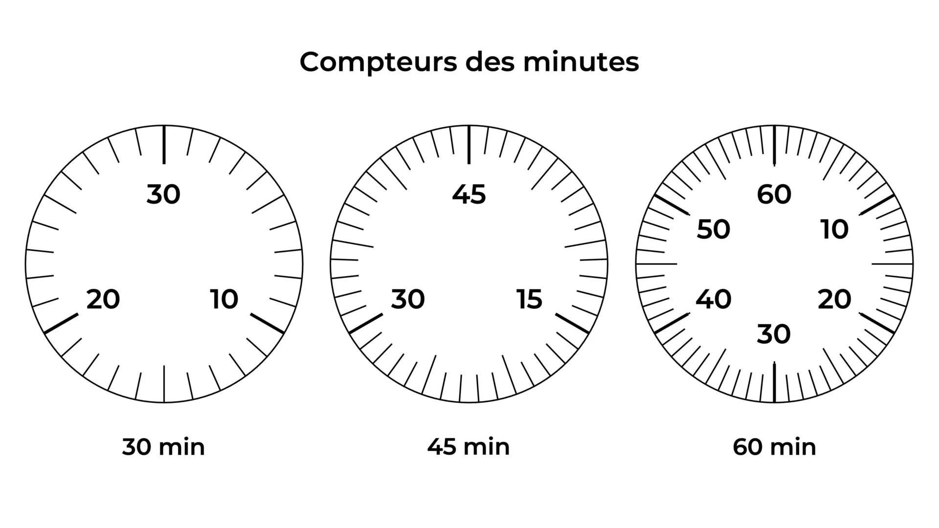
The minute counter indicates the number of minutes elapsed since the chronograph was started. It is driven from the chronograph seconds wheel by a finger or a lever/rocker system. Each time the seconds wheel has completed a full revolution — that is, with each minute elapsed — the minute counter advances by one step.
The minute counter is generally displayed on an auxiliary dial of smaller size than the main dial. Its usual position is at 3, 6 or 9 o’clock depending on the layout chosen by the manufacturer. Its capacity is 15, 30 or 60 minutes depending on the calibre. The 30- or 60-minute counter is the most common in modern chronographs.
9.2 The hour counter
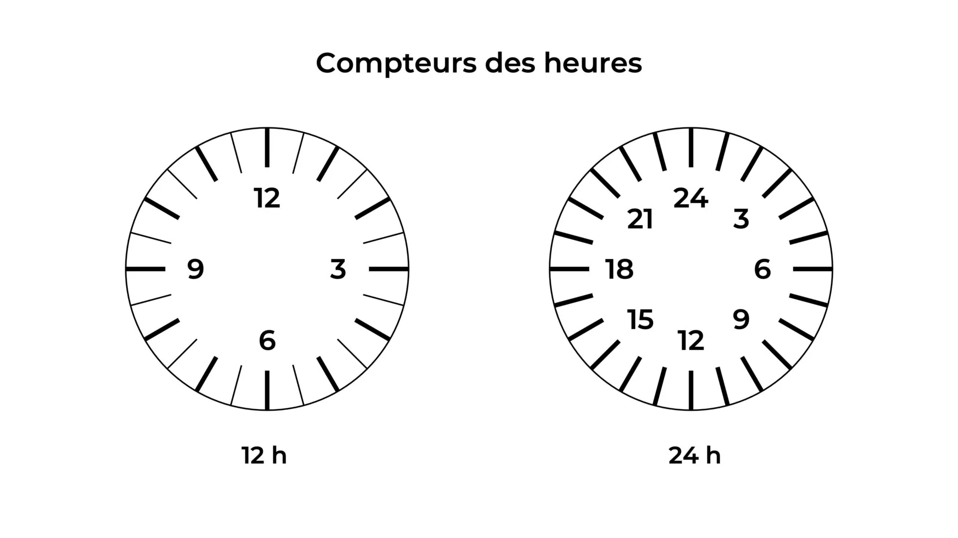
The hour counter indicates the number of hours elapsed since it was started. Its mechanism is similar to that of the minute counter: driven from the latter by a finger or a lever/rocker system, it advances by one step with each hour elapsed.
The most common capacity is 12 hours, allowing continuous measurements up to half a day. Some calibres have a 24-hour counter. The hour counter is generally displayed on a subdial opposite the minute counter.
Chronographs without an hour counter are designated by their maximum capacity in minutes. The presence of the hour counter adds a significant functional dimension for long-duration measurements and contributes to the visual balance of the dial.
10. Display modes
10.1 The central hand and subdials
The main display of the chronograph is provided by the central seconds hand, which makes one revolution per minute on the main dial. This hand is fixed to the axis of the chronograph seconds wheel and offers the best reading resolution. On a dial measuring 38 to 42 mm, the arc between two seconds represents approximately 4 to 5 mm, allowing an estimate to the fifth, or even the tenth, of a second depending on the nominal frequency of the movement.
The subsidiary dials of the minute counter and the hour counter complete the display. Their arrangement on the main dial is a major architectural decision. The tricompax arrangement — three subsidiary dials at 3, 6 and 9 o’clock — is one of the most widespread. In this case, the third counter indicates the seconds relative to the hour. The bicompax arrangement groups two subsidiary dials at 3 and 9 o’clock, or at 9 o’clock for the minutes and 6 o’clock for the hours. The indication of the seconds of the current time generally occupies the opposite space.
10.2 The indication of fractions of a second
The scale covered by the chronograph’s seconds hand is commonly subdivided into fractions. This subdivision of the second depends on the frequency of the oscillations of the regulating organ. Thus, if the regulating organ oscillates at 2.5 Hz, the chronograph’s seconds hand will make five jumps per second and the chronograph reading will achieve an accuracy of 1/5th of a second. If the regulating organ oscillates at 5 Hz, the chronograph’s seconds hand will make ten jumps per second and the chronograph reading will achieve an accuracy of 1/10th of a second.
11. The chronograph in grand complications
The two-pusher chronograph is frequently combined with other complications in fine watchmaking pieces. The most widespread association is the chronograph-calendar, combining the measurement of time with the indication of the Date / Calendar and Day. Perpetual calendar-chronograph watches represent a considerable mechanical challenge, requiring the integration of two complex mechanisms within a single case.
The combination of the chronograph with striking mechanisms (Minute repeater) represents one of the most demanding pairings in fine watchmaking. It requires rigorous management of available energy and a movement architecture allowing the striking mechanism and the chronograph to operate simultaneously without mechanical interference.
The flyback chronograph is a functional variant of the two-pusher chronograph. It allows the chronograph to be reset and instantly restarted with a single press of the second pusher. This simultaneous action — resetting and restarting — eliminates the dead time between two successive measurements, particularly useful for repetitive measurements of short durations.
The split-seconds chronograph is a variant offering a third pusher controlling a split-seconds hand. This hand follows the main hand, but can be stopped momentarily to note an intermediate time, then recalled to rejoin the main hand. This function allows the simultaneous measurement of two events sharing the same starting time.
12. The two-pusher chronograph in watchmaking tradition
The two-pusher chronograph represents the culmination of more than a century of technical evolution. Its most emblematic form, with column wheel, horizontal coupling and heart-piece zero-reset, stabilized in the first half of the 20th century. The great calibres of the 1930–1970 period defined the architectures that remain the technical references of the complication.
The manufacture of a two-pusher chronograph involves a number of parts considerably greater than that of a simple movement. A common chronograph calibre has between 250 and 350 parts, compared to 120 to 180 for a calibre without complication. Each of these additional parts requires precise manufacturing, testing and assembly. The assembly of a chronograph is significantly longer and more demanding than that of a basic movement.
The two-pusher chronograph remains today one of the most sought-after mechanical complications. Its presence in watchmaking production covers all levels of range, from high-end manufacture calibres to industrial production ébauches.
This page has been automatically translated from the French reference version using an artificial intelligence tool. Errors or inaccuracies may remain. If you notice any, especially if this is your native language, please feel free to report them to info@horopedia.org. Your contribution helps us improve the quality of the encyclopedia.
While awaiting their translation, images and videos remain temporarily displayed in French.
Thank you for your understanding.