
MENU
1. What is a milling cutter?
The Milling cutter is a rotary Cutting tool with multiple edges, designed to remove material through successive sections of chips. In watchmaking, where components are measured in hundredths or thousandths of a millimeter, the Milling cutter occupies a special place: it must combine geometric precision, cutting finesse, and great repeatability. It is found both in restoration workshops, in the form of small freehand Hand tools, and on numerically controlled machines tasked with machining plates, bridges, or pinions at an industrial pace.
This article offers a technical overview of the Milling cutters used in the watchmaking production chain. It successively covers Milling cutters intended for manual work, their constituent Materials, then Milling cutters mounted on machines, including those dedicated to Gear cutting — an emblematic operation of watchmaking mechanics.
2. General Principle of a Milling cutter
A Milling cutter consists of two main parts: a shank, by which it is held in the spindle of a machine or in the chuck of a hand tool, and an active part fitted with cutting edges. These edges, called teeth, are defined by several characteristic angles: the rake angle (which determines the ability to form the chip), the clearance angle (which avoids friction after cutting) and the helix angle (which ensures a progressive Entry into the Material). Depending on the drive mode, the Milling cutter rotates and the workpiece advances, or vice versa.
In horology, miniaturization imposes very specific constraints. Useful diameters frequently drop below one millimeter; cutting speeds remain high while forces must stay minimal so as not to deform the workpiece or weaken the tool. The geometry is therefore sharper than on common industrial Milling cutters, and the concentricity of the tool relative to its shank directly determines the quality of the surface obtained.
3. Milling cutters for manual work
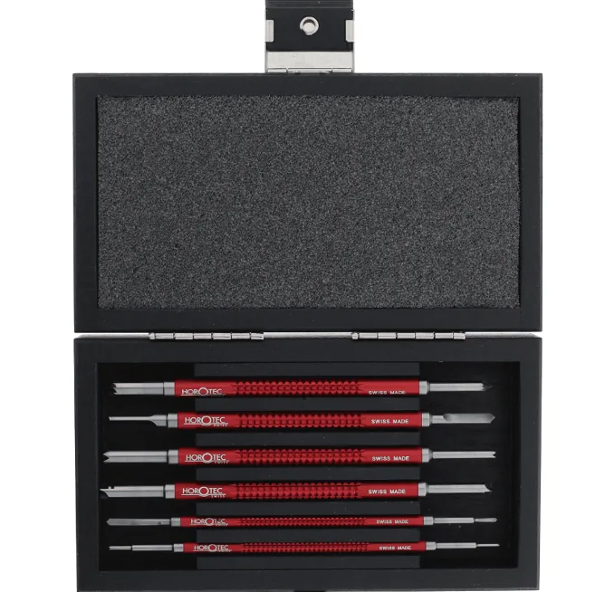
Various milling cutters on shank
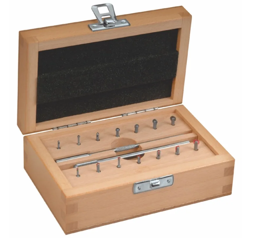
Roller milling cutters in steel and ruby/jewel on shank
Freehand work covers, in horology, the set of fitting, retouching, deburring and finishing operations carried out without a coordinate table. The horologist (watchmaker) then guides the tool by eye, relying on their free hand, on a support or on the piece itself. The milling cutters intended for these operations are small in size, generally mounted on a standardized shank — often with a diameter of 2.35 mm, sometimes 3 mm for more robust models.
3.1 Implementation
These milling cutters are driven by a handle, a hand chuck, a bench micromotor, a horologist’s lathe or a column drill. Rotation speeds typically range from a few revolutions to several tens of thousands of revolutions per minute, chosen according to the tool diameter, the material being machined and the nature of the operation.
3.2 Form milling cutters
Form Milling cutters reproduce, by simple plunge or by sweeping, a predefined profile. Their silhouette is the negative image of the geometry sought on the part: fillet, Groove, Unlocking (drop angle), bevel, shoulder profile. In traditional watchmaking, they are used to rework bridge contours, to form decorative recesses on plates, to open housings for Ruby / Jewel or oscillating weights, to perform repetitive chamfers. Their main advantage is to guarantee the consistency of the profile from one part to another.
From a geometric point of view, a distinction is made between constant-profile Milling cutters — whose shape is identical on each tooth and allows radial sharpening without loss of profile — and relieved-profile Milling cutters, more complex to resharpen, but often preferred for very specific profiles.
3.3 Ball Milling cutters
The ball Milling cutter, or spherical Milling cutter, has a hemispherical or spherical head at its tip. It is the ideal tool for hollowing out a cavity with smooth bottoms, Deburring a drilled hole, or adjusting the Entry of a Reaming. In horology, it is typically used to soften the Entry of a hole before setting a jewel, to slightly widen the diameter of a seat, or to perform a local Unlocking (drop angle) on an already machined part.
Common diameters range from a few tenths of a millimetre to several millimetres; the smallest ones allow very fine, almost pinpoint work, but require great mastery of pressure to avoid breaking the tool.
3.4 Wheel cutters
Under the term wheel cutters, we refer to tools whose active part has the shape of a thin wheel, mounted perpendicular to the axis of the shank. The cutting edge is developed on the periphery of the Disc, sometimes also on the Flanks. These cutters are used to create a Beveled edge or to finish it. They are generally made of hard Metal or synthetic Ruby / Jewel.
3.5 Materials of hand Milling cutters
The choice of cutting material determines the tool’s lifespan, the surface quality achieved, and the nature of the materials it will be able to work. Three families dominate in horology.
3.5.1 High-speed steel
High-speed cutting Steels, designated HSS in international nomenclature, remain widely used for profile Milling cutters and for working soft Materials (Brass, German silver, Aluminium Alloys). Their Hardness is more modest than that of carbide, but they offer good toughness and are easily resharpened. They tolerate shocks and feed rate variations, making them accessible tools for learning.
3.5.2 Hard Metal (Tungsten carbide)
Hard metal refers to sintered carbides, mainly Tungsten carbide bound by a cobalt matrix (WC-Co system). Their high Hardness — commonly between 1500 and 2000 HV depending on the grade — and their resistance to wear at high temperatures allow cutting speeds significantly higher than those permitted by high-speed steel, as well as the machining of hardened steels found in horology (pivot Axis, rods, pinions made of horological Steel). On the other hand, hard metal is more brittle to impact and costly to produce in small diameters.
Hard metal Milling cutters can be coated, by physical or chemical vapor deposition, with thin layers such as titanium nitride (TiN), titanium-aluminium nitride (TiAlN), or chromium nitride (CrN). These coatings lower the coefficient of friction, extend service life, and improve the surface finish of parts.
3.5.3 Synthetic Ruby / Jewel
Synthetic ruby is a variety of corundum (aluminium oxide Al₂O₃) coloured red by a residual chromium content. It has been produced industrially, since the work of Auguste Verneuil in the early 20th century, by flame-fusion melting of alumina powder onto a rotating seed, which produces a single-crystal boule. With a Hardness of 9 on the Mohs scale and around 2000 HV, it ranks among the hardest Materials available industrially, just after Diamond and cubic boron nitride.
As a Hand tools Material, synthetic ruby is mainly found on roller Milling cutters. It is not used for sharp cutting — which would require clean edges — but for fine abrasion, smoothing, and gentle fitting operations, particularly on hardened steels where the amount of material to be removed is minimal, but where the surface finish must be flawless.
4. Milling cutters for machines
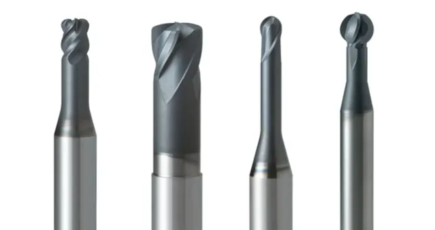
Various Milling cutters for machines (Milling machine, machining centre, etc.)
The shift from manual work to machine work does not change the principle of cutting, but profoundly transforms the possibilities. The movement of the Milling cutter is no longer guided by the eye and the wrist, but by slides, tables and controlled axes. Its rotation is driven by a spindle whose speed can, depending on the machine, reach several tens of thousands of revolutions per minute. The admissible forces increase, the speeds progress, and repeatability reaches levels inaccessible to even the most experienced operator. The machine Milling cutter is designed for these demands: it is more rigid, better balanced and cut according to geometries suited to automated cutting conditions.
4.1 Milling cutters for conventional Milling machines
The conventional Milling machine, whether horizontal, vertical or universal, still equips prototyping and small-batch workshops. A wide range of tools can be fitted to it. Two-flute Milling cutters, whose edges cut simultaneously on the end and on the periphery, are suitable for producing pockets, grooves and shoulders. Three-flute Milling cutters, disc-shaped, cutting on both faces and on the periphery, perform deep grooves and lateral Unlocking (drop angle)s. Face Milling cutters, of larger diameter, plane the faces; dovetail and T-slot Milling cutters produce particular slide profiles.
For horology, these Milling cutters are available in miniaturized versions, with a standardized shank, and benefit from the same carbide or high-speed steel grades as in general mechanics, sometimes coated to cope with the machining of special steels or hard bronzes.
4.2 Milling cutters for CNC machining centers
Computer-controlled machining centres, with three, four or five Axis, have profoundly renewed watchmaking production since the end of the 20th century. They allow complete Milling of main plates, bridges, oscillating weights, watch cases, etc., starting from raw blanks, by chaining operations with a single anchoring of the part. The associated Milling cutters are generally made of solid coated carbide, with an optimised geometry for very high rotation speeds — sometimes several tens of thousands of revolutions per minute on high-Frequency spindles.
Among these tools, one can distinguish end mill cutters with cylindrical shanks for contouring and surfacing, hemispherical Milling cutters for complex surfaces (particularly the 3D profiles of shaped cases), engraving Milling cutters for inscriptions and fine decorations, and Milling cutters for grooving. Microlubrication or neat cutting Oil, chosen according to the Material and the desired surface finish, generally accompanies the cutting process. On five Axis, the continuous orientation of the Milling cutter relative to the part allows for shortened, more rigid tool geometries, and accessibilities impossible to achieve on three Axis.
5. Milling cutters for cutting Gears
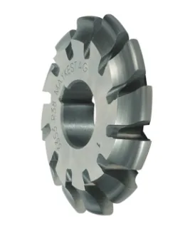
Milling cutter with epicycloidal profile
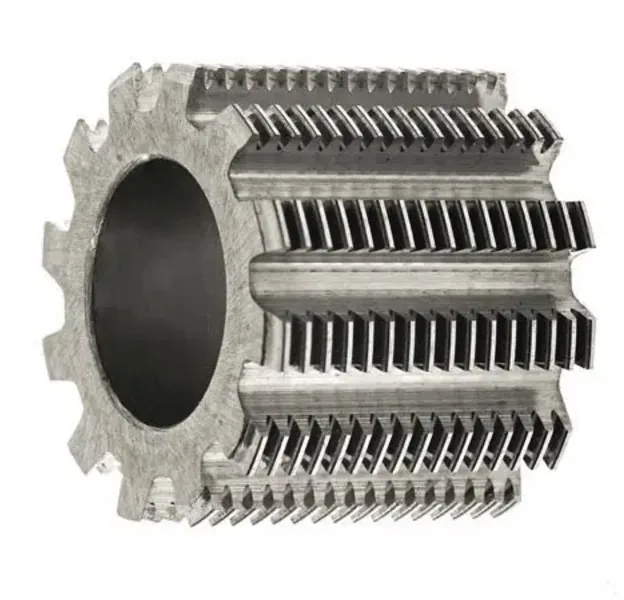
Hob milling cutter for hobbing cutting
The cutting of wheels and pinions constitutes the most emblematic operation in horological mechanics. The quality of the gearing — and therefore the regular transmission of torque from the mainspring to the regulating organ — depends directly on the precision of the tooth profile. The choice of milling cutters and processes is here governed by standards specific to horology, notably the NIHS standards (Standards of the Swiss Horological Industry), which define the profiles, modules, and tolerances.
5.1 The epicycloidal profile
Unlike general industrial mechanics, which favours the involute of circle profile, horology traditionally uses an epicycloidal profile (sometimes referred to as the “horological profile”). The tooth tip follows an epicycloidal curve while the root is radial. This choice is explained by considerations specific to small modules: better efficiency at low torque, lower sensitivity to variations in centre distance, and the ability to operate with very little Lubrication. More recently, derived or hybrid profiles — sometimes with a modified involute for certain applications — coexist alongside the traditional profile, particularly in pinions with high torque density or in winding Gear trains.
5.2 Constant profile module Milling cutters
The simplest method for cutting a Gear is index Milling. A Milling cutter whose profile exactly reproduces the shape of the tooth gap passes successively through each gap, the workpiece being indexed by an indexing device. These cutters, known as module cutters, are defined by their module (ratio of the pitch diameter to the number of teeth), their reference number of teeth and their profile. In horology, common modules range from 0.05 to about 0.50 mm. The process is still used for small batches, prototypes and rework on existing parts, as it is simple to implement and does not require specialized machinery.
5.3 Hobbing and hob cutters
For large batches, and when the profile precision must be maximal, Hobbing is used. The most widespread process is hob cutting, or hobbing: a helical Milling cutter, whose edges correspond to the generating rack of the toothing, meshes continuously with the wheel blank. The relative rolling motion, combined with the cutter’s feed, generates the exact shape of the teeth Flank by Flank. This process produces high-quality, geometrically very regular toothings, at high rates.
Hobbing cutting also exists in the form of shaping (mortising) with a pinion cutter (Fellows process) or with a rack cutter, particularly suited to certain geometries, such as internal gears or shouldered wheels. These machines, long built by specialized Swiss and foreign manufacturers, remain at the heart of horological gear train manufacturing workshops.
5.4 Finishing of gear teeth
After cutting, horological gear teeth are most often subjected to finishing operations. Burnishing of steel pinions, carried out using hard rollers that work-harden the surface of the flanks without removing material, considerably improves surface finish and wear resistance. For brass or copper alloy wheels, grinding or lapping operations with abrasive paste may possibly complete the work. These steps are no longer, strictly speaking, part of milling, but together with cutting, they form an inseparable whole in the manufacture of a precise gear train.
6. Selection criteria for a milling cutter
The selection of a Milling cutter, whether intended for hand or machine use, relies on the joint examination of several parameters. The Material of the workpiece determines the necessary cutting grade — high-speed Steel for Brass and soft Alloys, coated carbide for hardened Steels and superalloys, synthetic Ruby / Jewel for very fine abrasive touch-ups. The desired geometry determines the tool’s profile (cylindrical, spherical, conical, form, disc). The diameter, chosen according to the smallest radius of the workpiece, must remain as large as possible to preserve the tool’s rigidity and thus the surface quality. Finally, the nature of the operation (roughing or finishing) leads toward a Milling cutter with high chip evacuation capacity or, conversely, toward a Milling cutter with a high material Polishing rate.
The experience of the Horologist (watchmaker) or machining programmer comes into play at every step: choice of cutting speed, feed per tooth, depth of cut, Lubrication. A well-suited Milling cutter, but poorly used, will produce a mediocre result; conversely, a modest Milling cutter, but well mastered, may suffice for a large number of routine tasks.
7. Conclusion
Milling cutters occupy a pivotal position between traditional hand tooling and modern industrial production. Small form cutters, ball nose cutters or roller cutters, handled freehand on an antique piece, bear witness to a centuries-old practice; coated carbide cutters, driven at very high speed on a five-axis machining center, embody contemporary watchmaking. Between the two, gear-cutting cutters — module cutters or hobbing cutters — perpetuate a technical tradition typical of watchmaking: that of epicycloidal profiles, minute modules and tolerances measured in micrometers.
This page has been automatically translated from the French reference version using an artificial intelligence tool. Errors or inaccuracies may remain. If you notice any, especially if this is your native language, please feel free to report them to info@horopedia.org. Your contribution helps us improve the quality of the encyclopedia.
Pending their translation, images and videos remain temporarily displayed in French.
Thank you for your understanding.