
MENU
1. General description
The sliding pinion (or shifting pinion) is a cylinder made of steel which has the particularity of having teeth at each of its ends. It commonly belongs to the winding mechanism and to the time-setting mechanism. Its axis is crossed by a square-section hole that allows it to fit onto the winding stem. This square fit allows the winding stem to drive the sliding pinion, when the crown is turned. Since the length of the winding stem’s square section exceeds the length of the sliding pinion, the latter can slide linearly along the axis of the stem. A groove machined at the center of the sliding pinion allows the lever of the rocker to be housed there. When the crown (and thus the winding stem) is pushed in, the lever/rocker positions the sliding pinion against the winding pinion, with which it meshes via a disengageable unidirectional Breguet-type toothing. When the crown (and thus the winding stem) is pulled out, the setting lever actuates the lever/rocker, which slides the sliding pinion so that its second toothing now meshes with the time-setting mechanism.
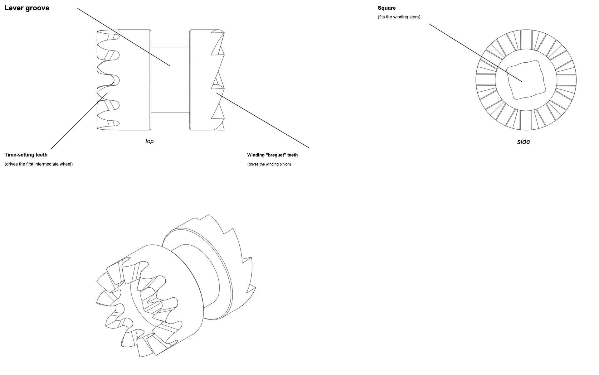
Figure 1
Diagram of a sliding pinion
Click on the thumbnail to enlarge it
Figure 2
Lever/rocker between the winding and hand-setting mechanisms
Click on the animation to enlarge it
2. History
The invention of the sliding pinion can clearly be attributed to Antoine Le Coultre when he invented, in 1847, the winding mechanism with a lever/rocker. This made it possible from then on to wind and set the time on a watch without a key, using the same control (the crown). In almost two centuries, the mechanism has not undergone any significant evolution and remains the mechanism essentially used today.
3. Artisanal manufacturing of a sliding pinion
A lathe is enough to fully manufacture a sliding pinion. Few turning operations are needed (unlocking of the two faces to free the teeth and the groove of the lever). It is still necessary to drill the pinion. If a small milling cutter allows it, a square hole can be milled directly on the lathe. The other solution consists of drilling a cylindrical hole and then manually filing the square. Before removing the pinion from the lathe, its two sets of teeth can be milled directly and its decoration carried out.
4. Industrial production of a sliding pinion
As with most small-diameter circular components, the automatic lathe is the ideal machine to produce sliding pinions regardless of the quantities involved. This allows for the quick completion, in a single cycle, of all operations (turning, cutting, milling of the square). Whatever quality is desired, machining a sliding pinion using this method will only take a few minutes.
This page was automatically translated from the reference French version using an artificial intelligence tool. Errors or inaccuracies may remain. If you notice any, especially if this is your native language, please feel free to report them to info@horopedia.org. Your contribution helps us improve the quality of the encyclopedia.
Pending their translation, images and videos remain temporarily displayed in French.
Thank you for your understanding.