
DISTRIBUTION MECHANISM – SWISS LEVER ESCAPEMENT
MENU
Video: Discussion on the Swiss lever escapement with Dominique Büser
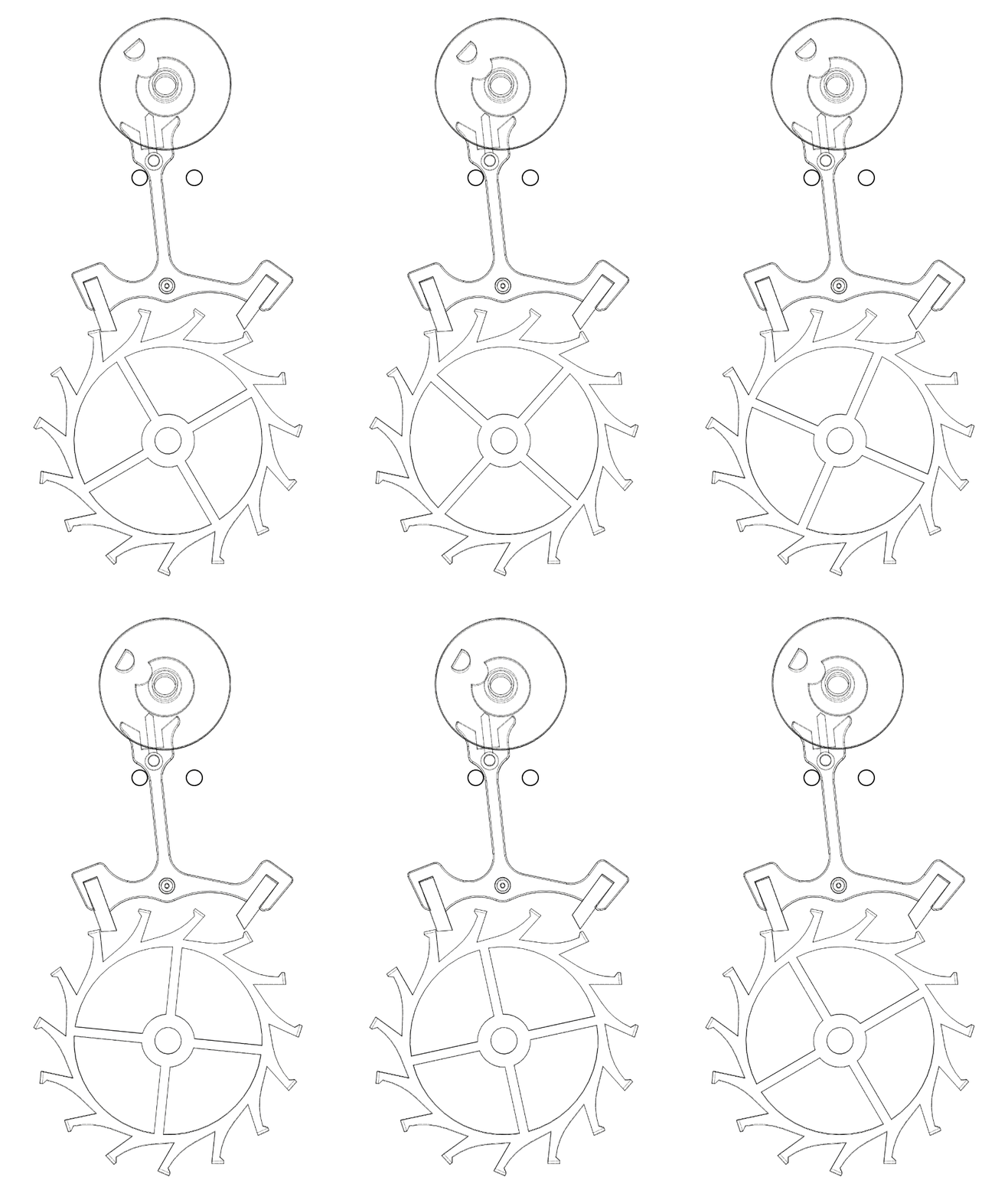
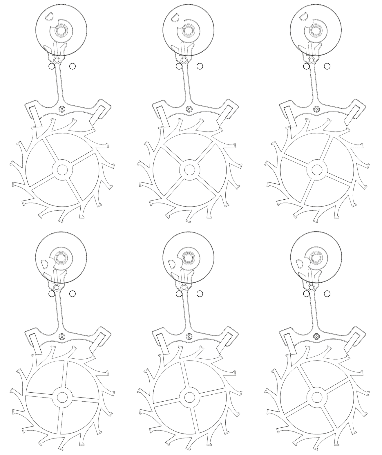
Operating speed 1:4
Real operating speed (21,600 vph)
Click on the animations to enlarge them
1. General information
In general, the escapement is the distribution mechanism of a watch, a pendulum clock, or a clock. The Swiss lever escapement is valued for its robustness, precision, and relative ease of production.
From its appearance, this escapement established itself as the standard, both for its technical qualities and its economic qualities.
2. History
The Swiss lever escapement appeared in the second half of the 19th century, improving on the principles of the older and less efficient English lever escapement.
It was around 1842 that Georges-Auguste Leschot, a Swiss horologist, contributed to the industrialization of this escapement, which allowed its widespread distribution. Over the decades, Swiss manufactures perfected it, making it a pillar of modern watchmaking.
3. Role of the escapement
The escapement has two main roles. First, it must keep the finishing train stopped in order to release it punctually and regularly. Indeed, if the escapement did not exist, all the energy from the barrel would dissipate within a few seconds through the finishing train, which would run away. The escapement therefore blocks the energy of the train and releases it periodically … hence its name. (Note that in the animation above on the left, the escape wheel advances in small jumps, but is stopped most of the time).
The escapement must also maintain the oscillations of the regulating organ by transmitting a regular impulse to it. Since the regulating organ is an oscillator, the escapement’s role is also to convert a linear motion (the rotation of the finishing train) into an oscillatory motion (the oscillations of the balance-hairspring) (animations above).
4. Description and components
The Swiss lever escapement belongs to the family of free escapements.
The Swiss lever escapement is composed of the following elements:
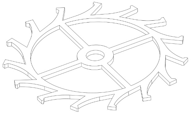
The escape wheel. It is generally made of steel, nickel-phosphorus (UV-LIGA), or silicon (DRIE (Deep Reactive Ion Etching))
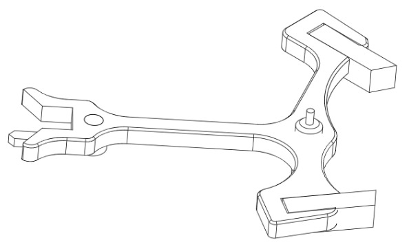
The pallets (lever). It is generally made of steel, or even brass or Glucydur, with pallet stones made of ruby / Jewel, or entirely in nickel-phosphorus or Silicon.
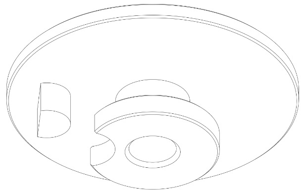
The double roller. It consists of the large and small rollers, connected to each other by a Pipe. It is made from relatively ductile Materials, suitable for staking (Steel, Brass or Glucydur, etc.). Being too brittle, Silicon is not suitable for making double rollers. The Impulse pin (roller jewel), generally made of Ruby / Jewel (synthetic corundum), is either burnished or glued onto the large roller.
5. Advantages and disadvantages of the Swiss lever escapement
Advantages
- Precision: the Swiss lever escapement is a well-developed escapement that allows excellent chronometry to be achieved.
- Reliability: it withstands shocks and position variations particularly well. It is thus perfectly suited to use in wristwatches.
- Industrial production: regardless of the materials used in the manufacture of its components, the production of Swiss lever escapements is well controlled and cost-effective.
- After-sales service: with the exception of silicon escapements, the Swiss lever escapement can be regulated(escapement-making (finishing))easily, regardless of the age of the watch.
Drawbacks
- Friction: although the materials of the escapement components (steel-ruby, silicon) are chosen to minimize friction, it remains significant. Thus, the steel teeth of the escape wheel interact with the ruby pallet stones of the pallets (lever) exclusively through sliding friction. The Swiss lever escapement alone absorbs about 30% of the barrel’s nominal energy. Silicon escapements now achieve better efficiency.
- Maintenance: in traditional manufacturing (steel and ruby), it requires delicate lubrication, which must be renewed regularly to ensure good performance and limit wear. Silicon escapements also offer a solution to this problem, as most of them can operate without lubrication.
6. Operation
The operation of the Swiss lever escapement can be divided into four phases that unfold unchangingly according to the same cycle with each vibration of the regulating organ. These four phases are:
- Rest
- Unlocking (drop angle)
- Impulse
- Safety features
Let us detail below the action of each component during each of the four phases:
1. Rest
During this phase, the entire finishing Train (wheel train) is stopped, blocked by the escapement.
Double roller:
It is the only element of the escapement then in motion.
During the rest phase, the double roller freely performs its ascending supplementary arc α, then its descending supplementary arc β (see below, Figure 1, point 1). This is the angle traveled by the double roller (and therefore by the balance) during the resting period of the escape wheel and the pallets.
Pallets (lever):
The pallets are at rest. The pallets’ rod is held against the banking pin (below, Figure 1, point 2) by the escape wheel tooth under the effect of the draw (see the the draw tab).
Escape wheel:
Like the pallets, the wheel is at rest. One of its teeth rests on the resting plane of the pallet stone (see below, Figure 1, point 3).
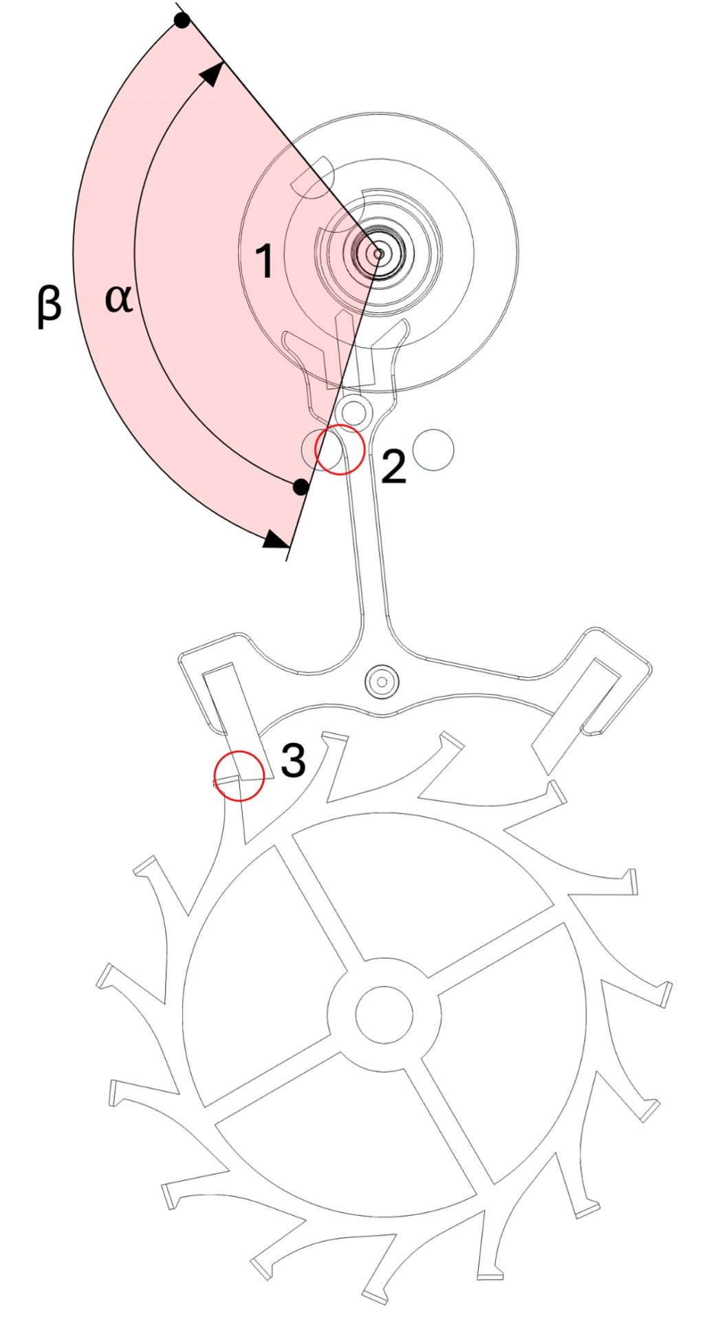
Figure 1: The rest
Click on the thumbnail to enlarge it
2. Le dégagement
Durant cette phase, la roue d’échappement et le rouage de finissage reviennent très légèrement en arrière.
Double plateau:
La phase du dégagement débute lorsque la cheville de plateau entre en contact avec la fourchette (Figure 2, point 4). La phase de dégagement du double plateau correspond à l’angle α qu’il parcourt, tandis que la cheville de plateau pousse la fourchette de l’ancre (Figure 3).
Ancre:
La phase de dégagement de l’ancre correspond à l’angle β qu’elle parcourt au cours de l’action de la dent de la roue d’échappement sur le plan de repos de la palette (Figure 3). La phase de dégagement se termine lorsque la dent de la roue se trouve, théoriquement, sur le bec de repos de la palette (Figure 4, point 5).
Roue d’échappement:
Par le levier que constituent l’ancre et sa géométrie, la roue d’échappement recule légèrement durant la phase de dégagement (recul géométrique, env. 0,15-0,25°) puis poursuit son mouvement en se détachant brièvement du plan de repos de la palette (recul dynamique, env. 0,04°). La somme du recul géométrique et du recul dynamique définit l’angle γ (Figure 3). Enfin, la roue d’échappement reprend son sens de rotation habituel sous l’effet de l’énergie motrice. Comme pour l’ancre, on considère que la phase de dégagement se termine lorsque la dent de la roue se trouve, théoriquement, sur le bec de repos de la palette (Figure 4, point 5).
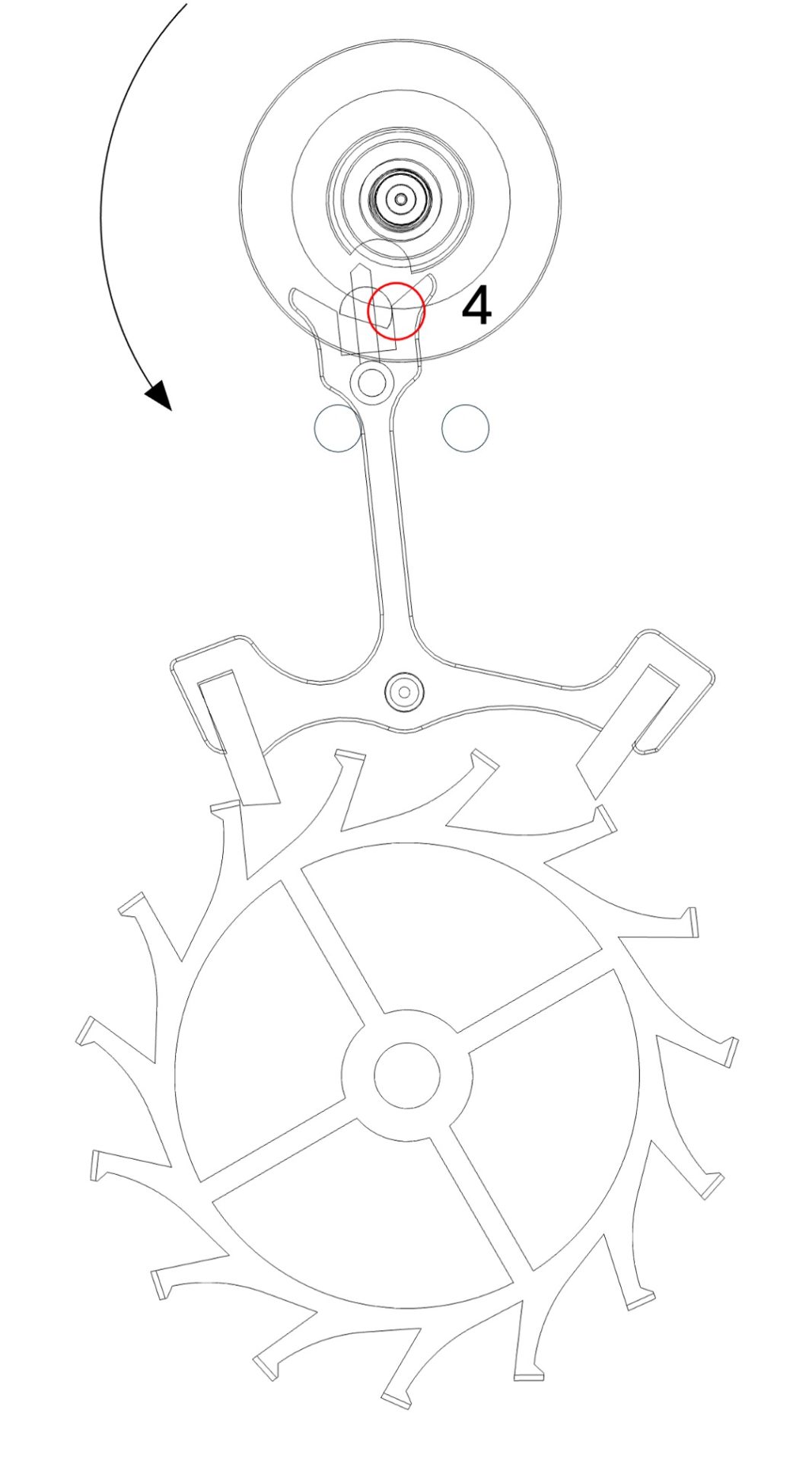
Figure 2
Start of unlocking
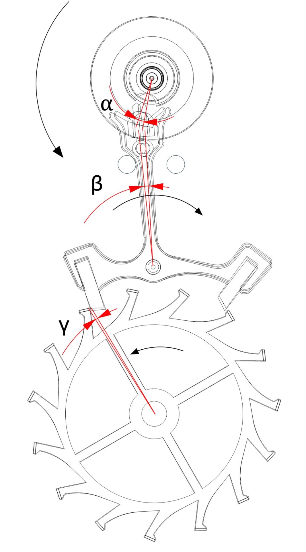
Figure 3
Unlocking phase
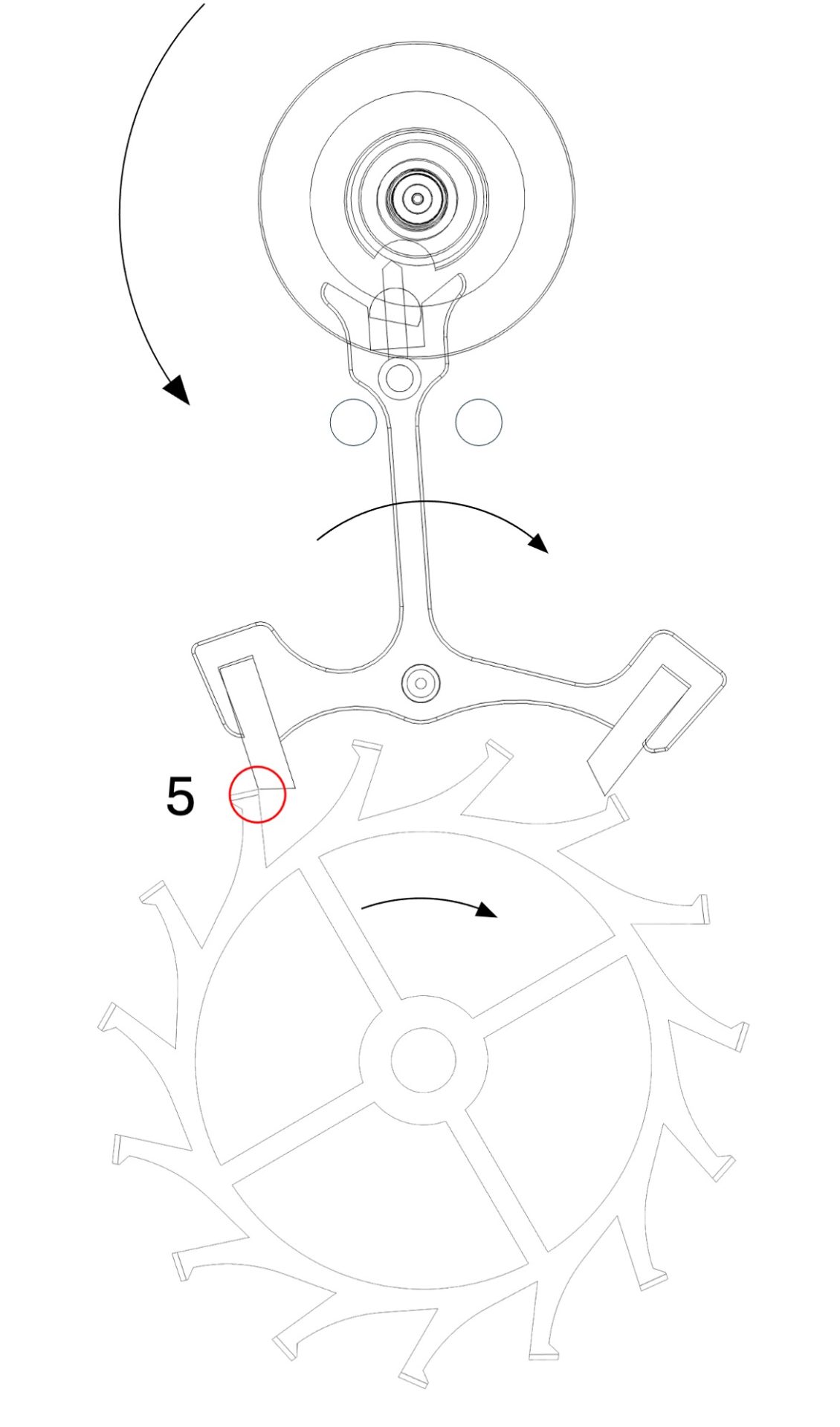
Figure 4
End of unlocking
Click on thumbnails to enlarge them
3. Impulse
It is during this phase that the escapement transmits the energy received from the barrel via the finishing Train to the regulating organ.
Double roller:
The start of the impulse occurs when the fork catches up with the impulse pin (Figure 5, point 6). The impulse phase of the double roller corresponds to the angle δ travelled while the fork pushes the impulse pin (roller jewel) (Figure 6). The impulse phase begins before the dead point and ends after it (Figure 7).
Pallets (lever):
The impulse phase of the pallets (lever) corresponds to the angle ε (Figure 6) that it describes while the impulse tip of the wheel tooth travels across the impulse plane of the pallet stone. The impulse phase ends when the impulse tip of the wheel tooth is on the impulse tip of the pallet stone (Figure 8).
Escape wheel:
The impulse phase of the escape wheel corresponds to the angle it travels during the action of the impulse plane of its tooth on the impulse plane of the pallet stone. The impulse begins when the resting tip of the pallet stone comes into contact with the impulse plane of the pallet stone (Figure 5, point 7) and ends when the impulse tip of the tooth reaches the impulse tip of the pallet stone (Figure 8, point 8).
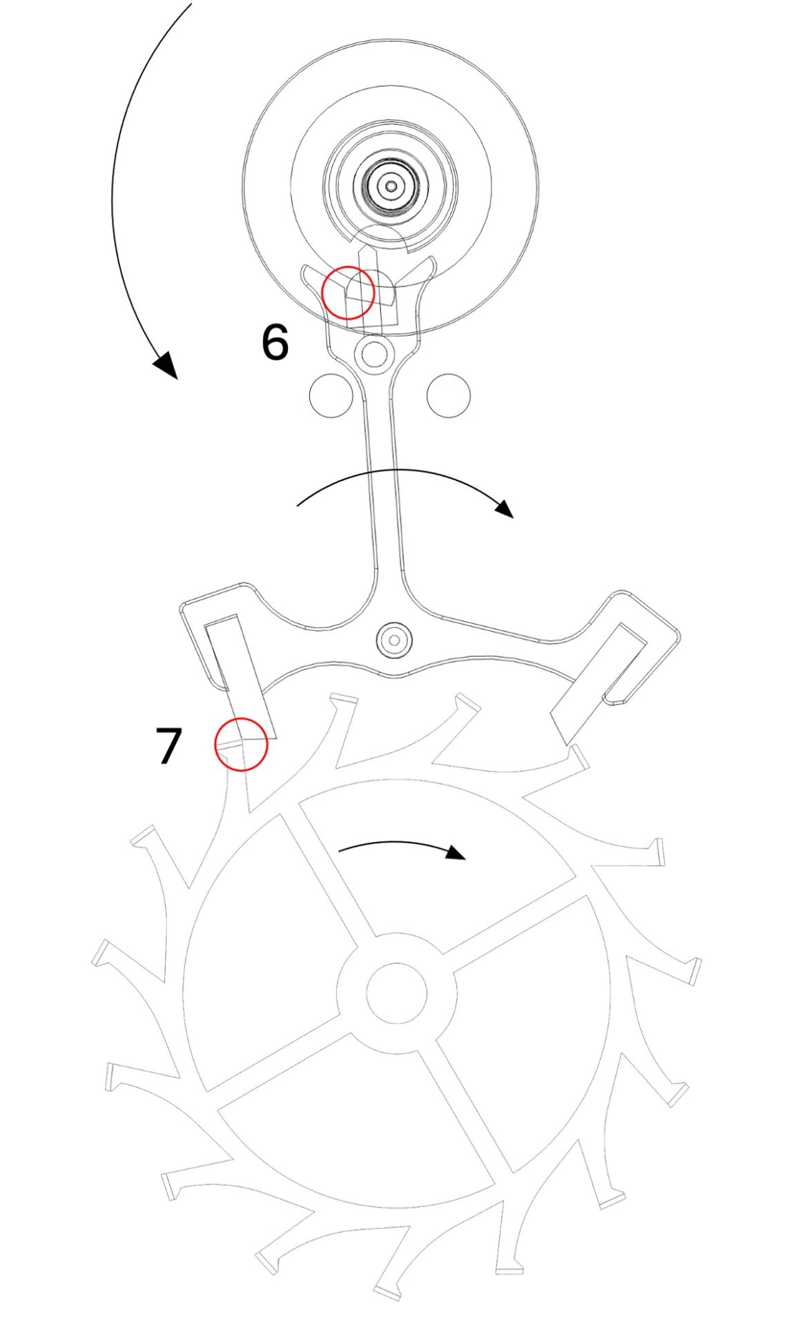
Figure 5
Beginning of the impulse
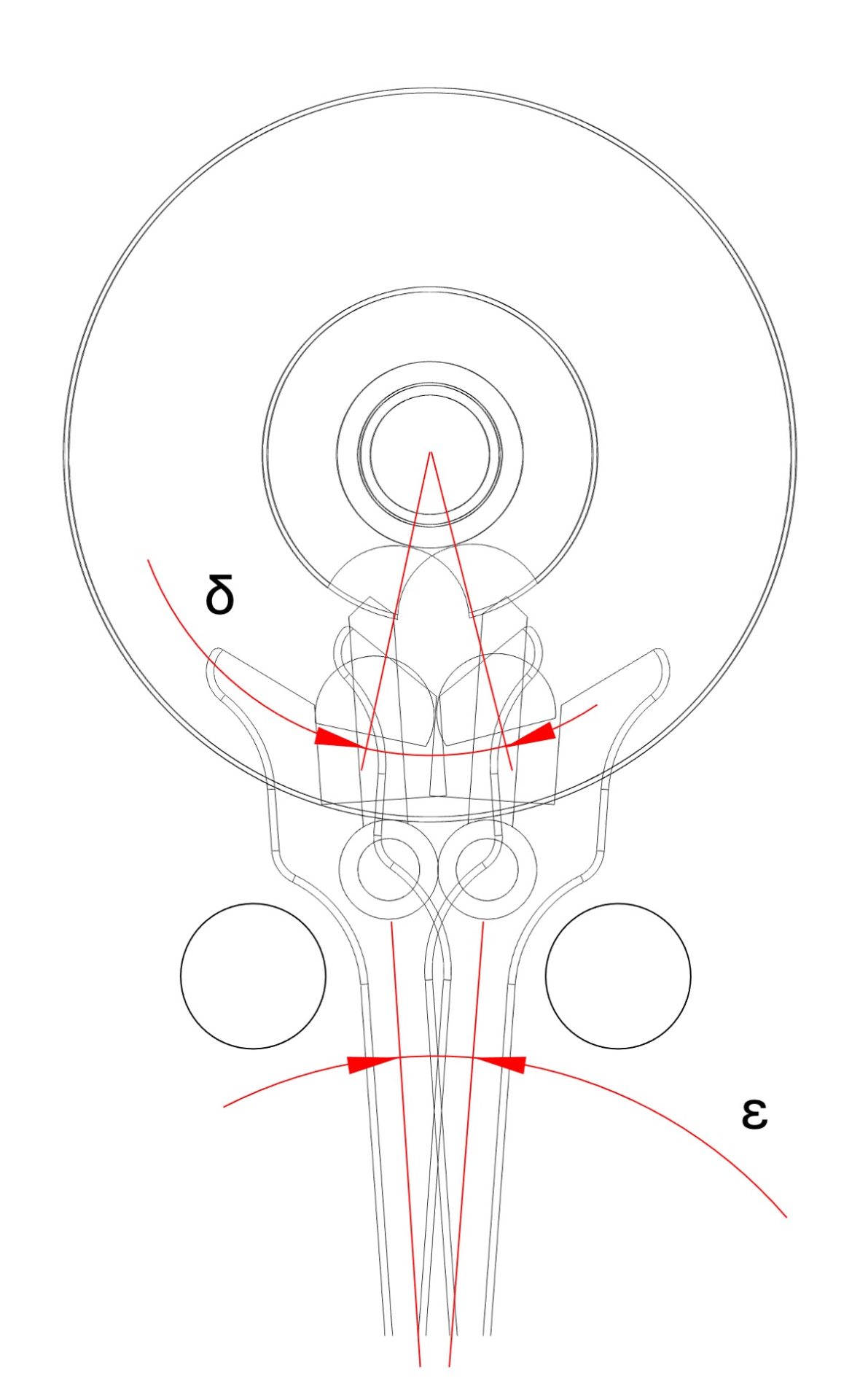
Figure 6
Impulse phase
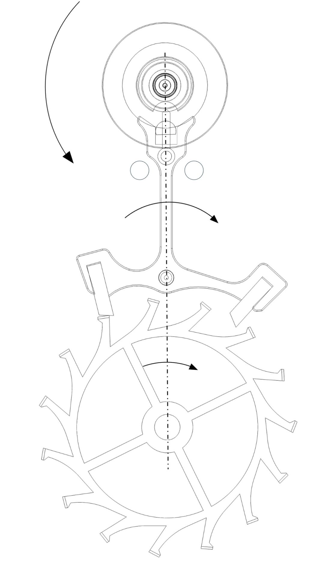
Figure 7
Dead point (Impulse)
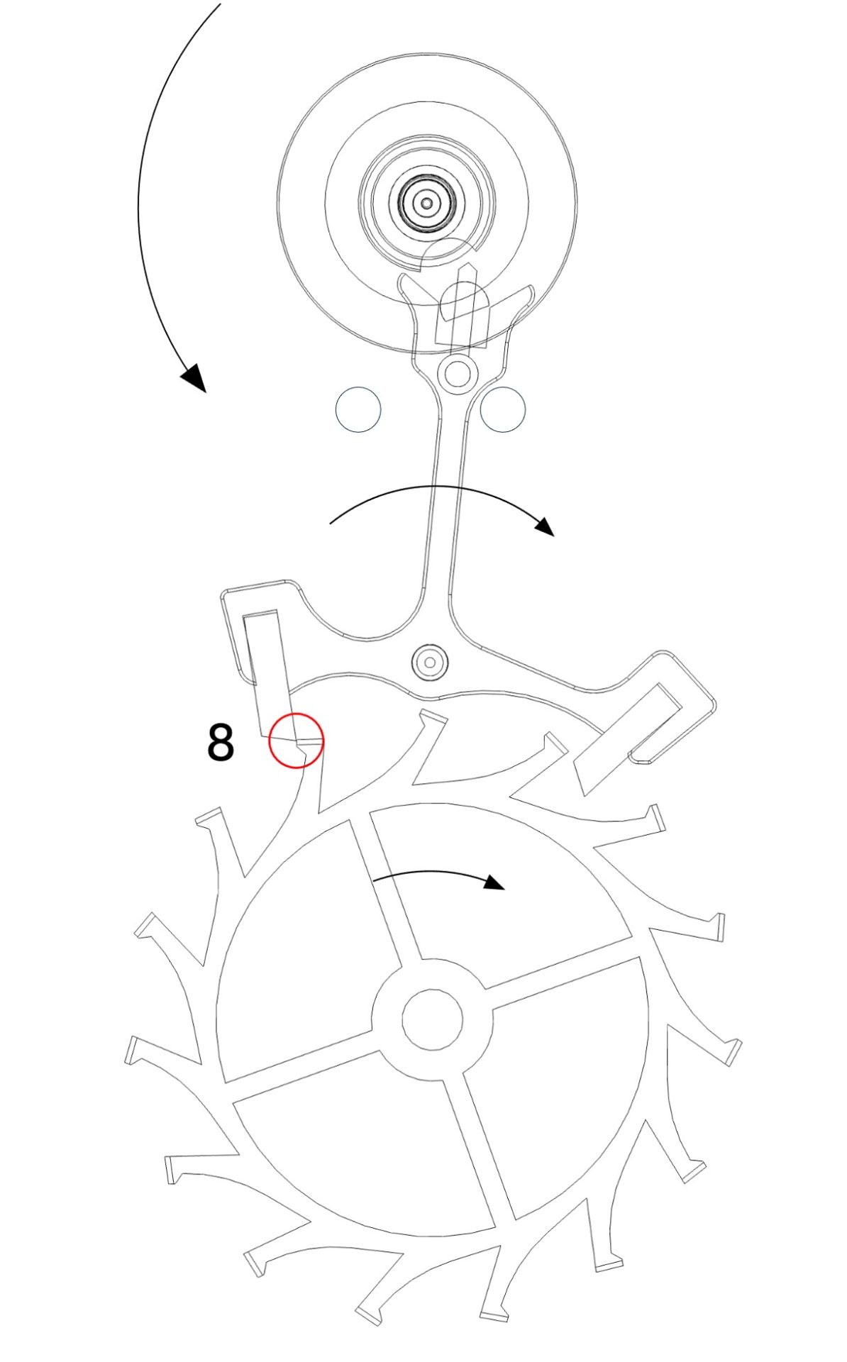
Figure 8
End of the Impulse
Click on the thumbnails to enlarge them
4. Les sécurités
Les sécurités sont des angles parcourus par la roue d’échappement et l’ancre, en pure perte, juste après la phase d’impulsion.
Double plateau:
Au début de la phase des sécurités, la cheville de plateau perd le contact avec la fourchette de l’ancre (Figure 9, point 9). Le double plateau entame alors librement son arc supplémentaire ascendant α’ puis son arc supplémentaire descendant β’ (Figure 9).
Ancre:
L’angle de sécurité de l’ancre s’appelle le chemin perdu. C’est l’angle que parcourt la baguette de l’ancre dès lors que la dent de la roue d’échappement entre en contact avec le plan de repos de la palette (Figure 10, point 11) et l’instant où la baguette de l’ancre entre en contact avec la goupille de limitation sous l’effet du tirage (Figure 11, point 12).
Roue d’échappement:
L’angle de sécurité de la roue d’échappement s’appelle la chute. La chute correspond à l’angle parcouru par la roue dès lors qu’une de ces dents quitte le plan d’impulsion de la palette (Figure 9, point 10) et qu’une autre dent entre en contact avec le plan de repos de l’autre palette (Figure 10, point 11).
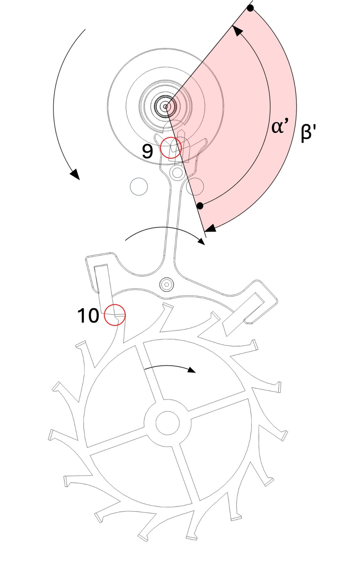
Figure 9
Beginning of the Drop (impact)
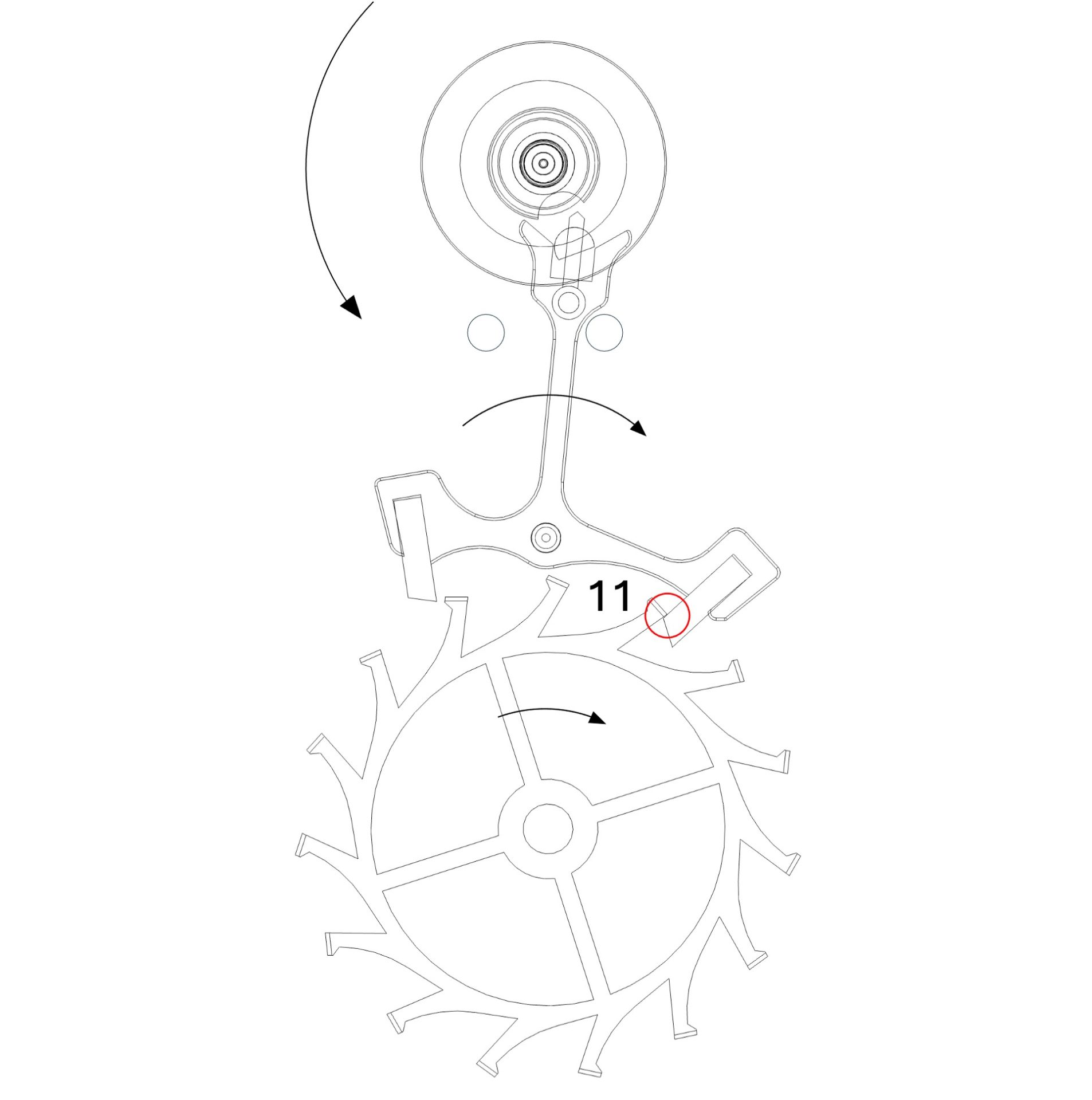
Figure 10
End of drop (impact) and start of backlash
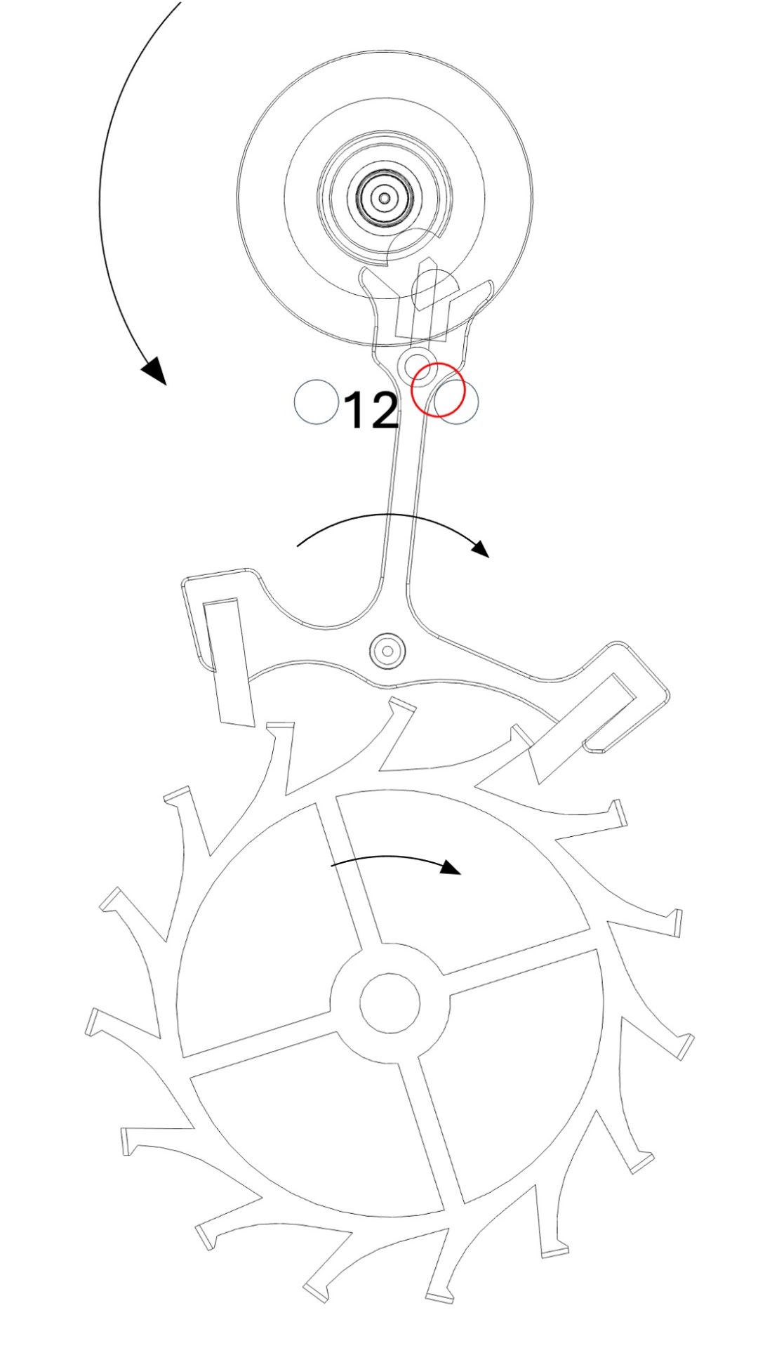
Figure 11
End of backlash
Click on the thumbnails to enlarge them
Note:
For a complete view of how the Swiss lever escapement works, please refer to the two animations at the top of this page.
7. Definition of different angles
1. The double roller (de facto the balance)
Description of the different angles of the double roller (and therefore of the balance) during two vibrations (one oscillation).




(*) Important:
When the escape wheel performs its dynamic recoil (see the operation tab), the Pallets (lever) continues its movement, driven by the Impulse pin (roller jewel). When the Escape wheel resumes its forward motion, the wheel’s tooth regains contact with the impulse plane of the Pallet stone of the Pallets (lever), and the Impulse phase transmitted to the balance begins. During this period, contact between the Impulse pin (roller jewel) and the Fork of the Pallets (lever) was briefly interrupted and the double roller (and therefore the Balance) has freely traveled a small angle between the end of the Unlocking (drop angle) and the beginning of the Impulse (angles described above as the free travel of the Balance).
2. The Pallets (lever)
2.1 Total lift angle  (Figure 12)
the total lift angle of the pallets (lever) corresponds to the displacement of the rod of the pallets (lever) between the two banking pins (or the limit stops). It corresponds to the sum of the unlocking, impulse, and backlash angles, and its value is generally between 12° and 20°.
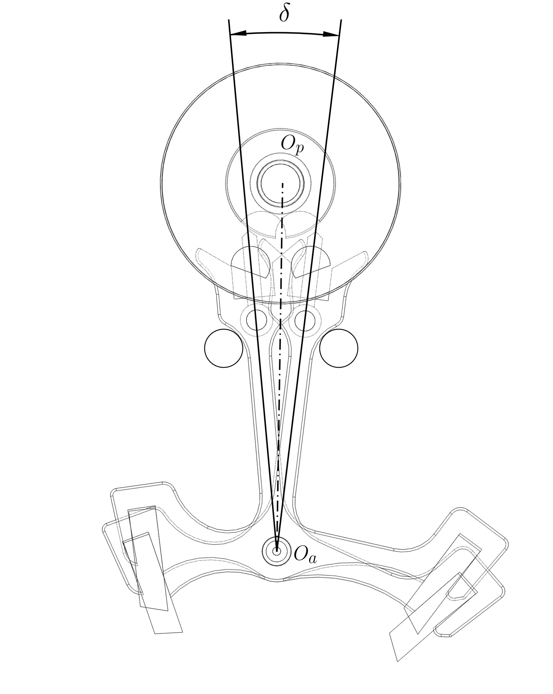
Figure 12
lift angle of the pallets (lever)
click on the thumbnail to enlarge it
2.2 virtual total depth angle  (Figure 13)
it is the angle between the resting tip of the pallet stone (see the pallets (lever)) and the point where the tooth of the escape wheel falls onto the resting plane of the pallet stone of the pallets (lever).
2.3 Backlash angle  (Figure 13)
This is the angle traveled by the pallets (lever) between the end of the impulse and the fork resting against the banking pin (or the limiting stop) (see operation)
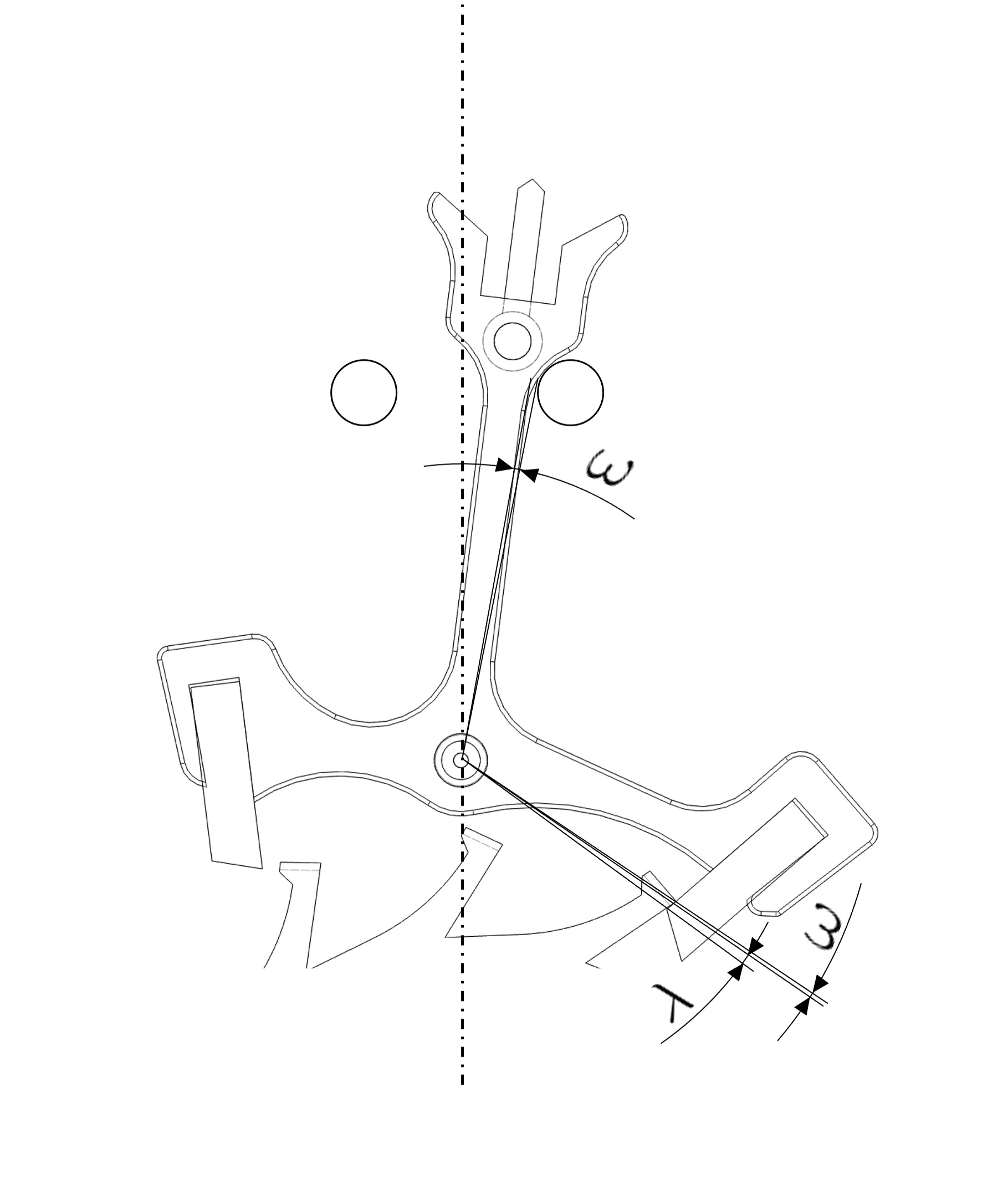
Figure 13
Virtual depth and backlash angles of the pallets (lever)
Click on the thumbnail to enlarge it
2.4 Total depth angle  (Figure 14)
The total depth angle corresponds to the sum of the virtual depth angles (Figure 13 – ) and backlash (Figure 13 – )
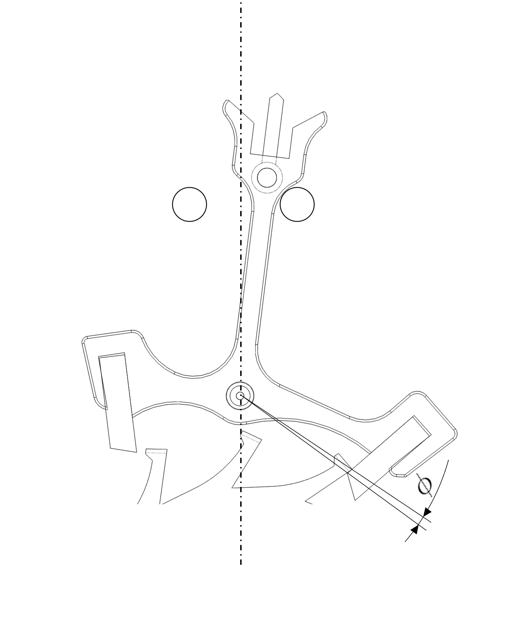
Figure 14
Total depth angle of the pallets (lever)
Click on the thumbnail to enlarge it
8. Components preventing overbanking
While the balance travels through its supplementary arc (ascending or descending), the pallets (lever) rests against one or other of the banking pins (or the bankings) due to the effect of draw (see draw tab).
If a shock overcomes the draw torque, the pallets (lever) swings against the other banking pin. At the end of the additional descending arc of the balance, the impulse pin (roller jewel) strikes against the back of the horn (lug), which causes the watch to stop immediately. (Figure 15).
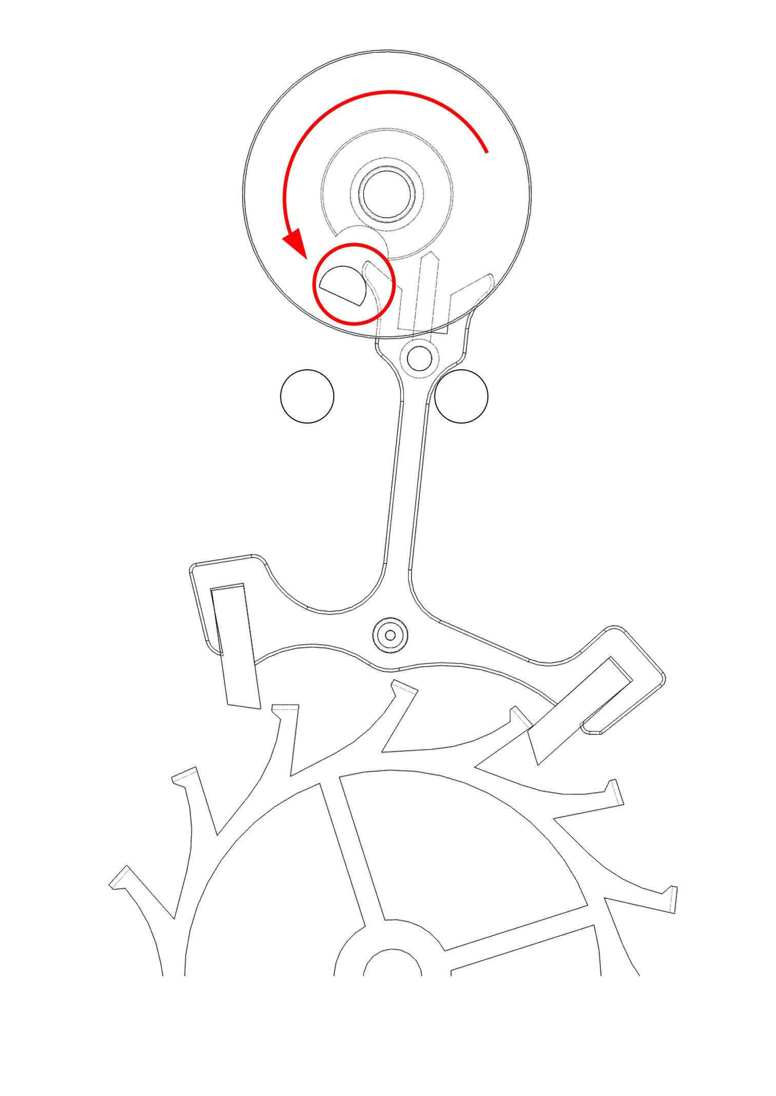
Figure 15
Overbanking situation
Click on the thumbnail to enlarge it
To prevent overbanking, the Swiss lever escapement has four components:
When the balance travels through its supplementary arc, the dart (safety pin) rests against the edge of the small roller preventing the pallets (lever) from tipping against the other banking pin and thus preventing overbanking (Figure 16).
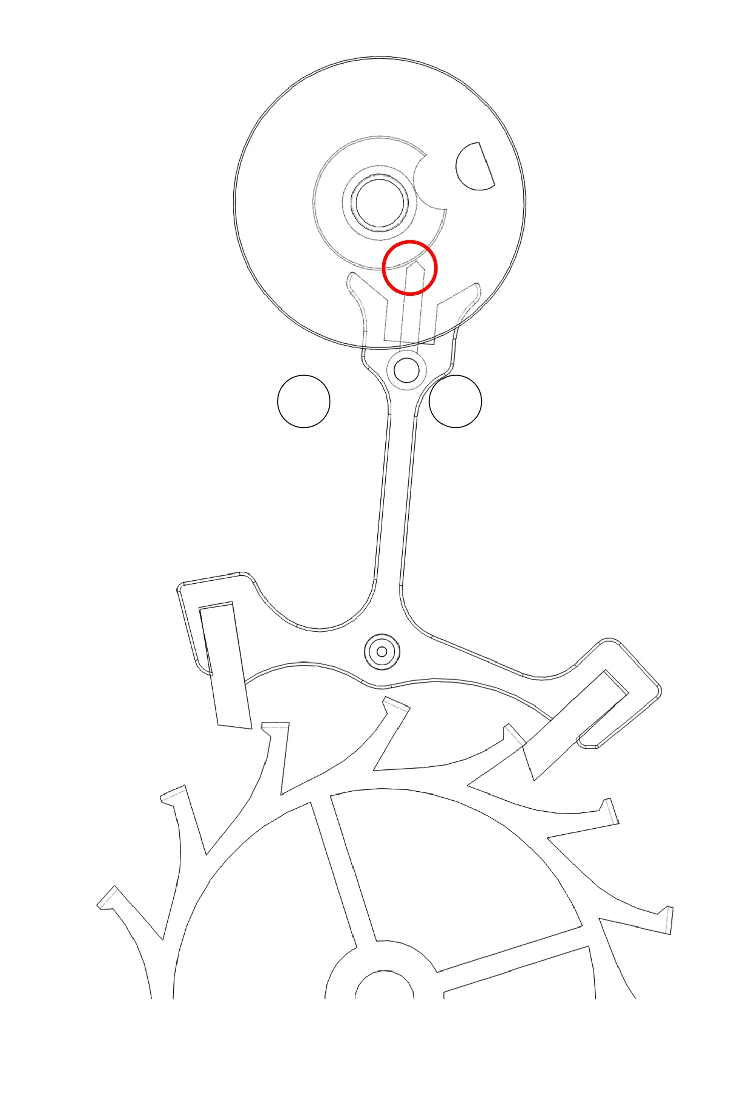
Figure 16
Components preventing overbanking (dart and small roller)
Click on the thumbnail to enlarge it
The small roller has a notch aligned with the impulse pin. During the unlocking and impulse phases (see operation), this notch allows the dart to pass through and the pallets to swing normally from one pin to the other. During these phases, it is the inside of the horns that comes to rest against the impulse pin, thus preventing overbanking (Figure 17).
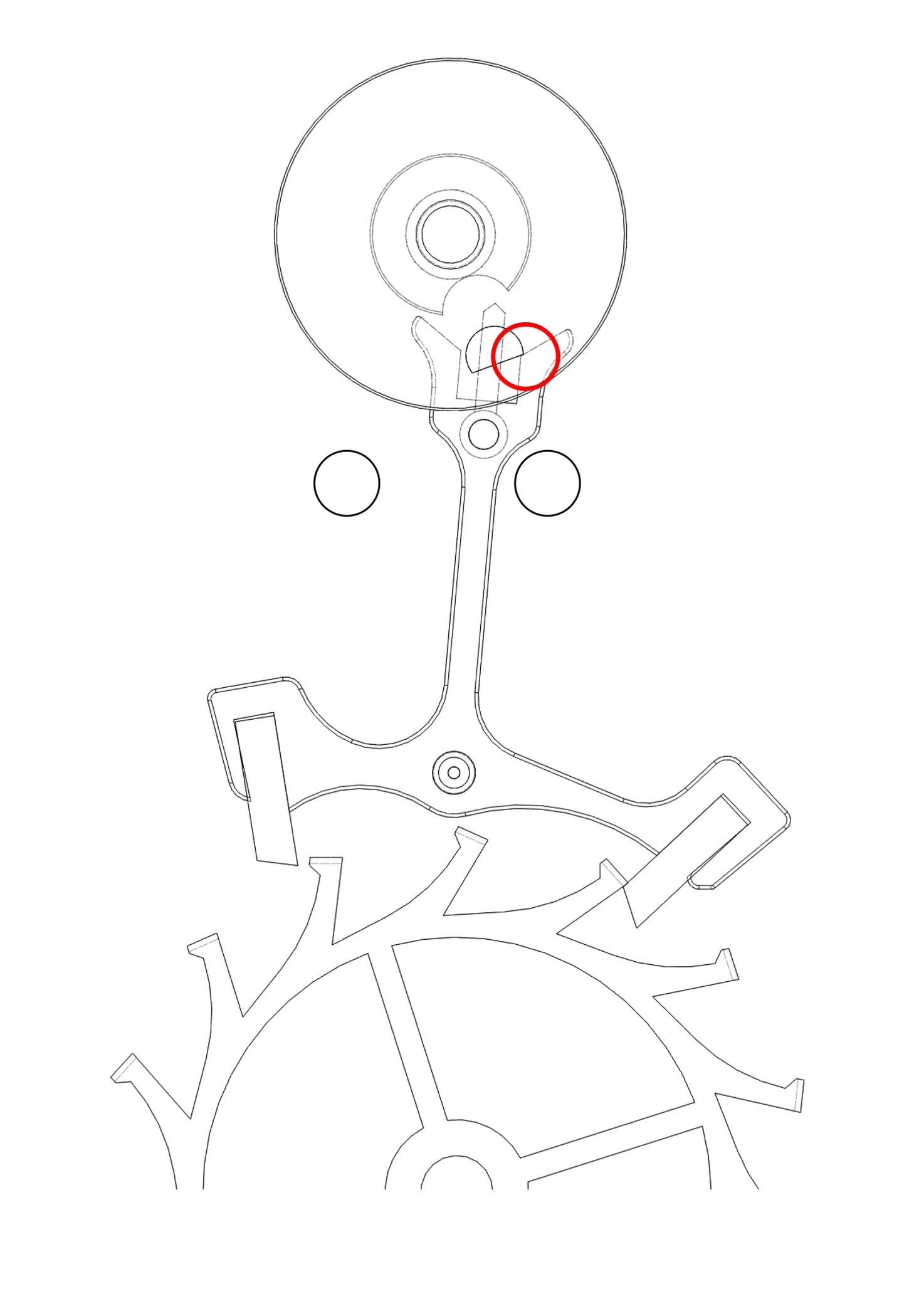
Figure 17
Components preventing overbanking (horn and impulse pin)
Click on the thumbnail to enlarge it
9. The shocks
The various shocks of the Swiss lever escapement can be heard. This is the “tick-tock” of mechanical watches. But when the human ear perceives a tick or a tock, the escapement has actually produced five sounds resulting from five shocks. These sounds are so close together that the ear only hears one (a tick or a tock).
Analyzing these sounds, based on the intensity of each one and the spacing between them, makes it possible to detect malfunctions or incorrect adjustments of the escapement. Similarly, the graphs from a timing machine make it possible to identify problems related to the escapement. For each vibration, these five shocks are as follows:
- The unlocking (drop angle)
- The beginning of the escape wheel’s Impulse
- The beginning of the Balance’s Impulse
- The end of the Drop (impact)
- The end of the Backlash
1. Unlocking (drop angle)
The first shock of a vibration occurs when the Impulse pin (roller jewel) comes into contact with the inside of the Fork (Figure 18).
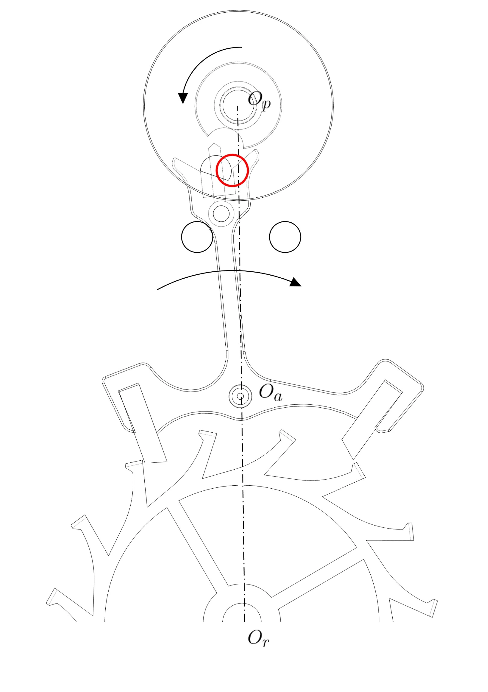
Figure 18
Shock during Unlocking (drop angle)
Click on the thumbnail to enlarge it
2. Start of the escape wheel impulse
Shortly after unlocking, the resting tip of the escape wheel falls onto the impulse plane of the pallet stone. This is the second impact (Figure 19).
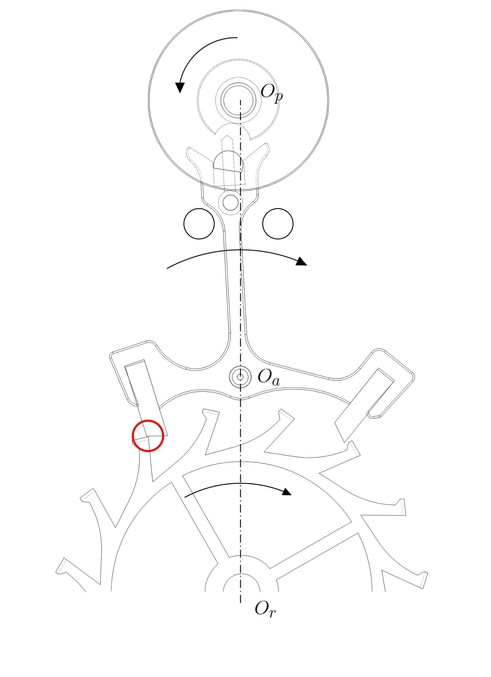
Figure 19
Impact at the start of the escape wheel impulse
Click on the thumbnail to enlarge it
3. Start of the balance impulse
The fork catches up with the impulse pin and transmits its impulse to the balance via the double roller. This is the third impact (Figure 20).
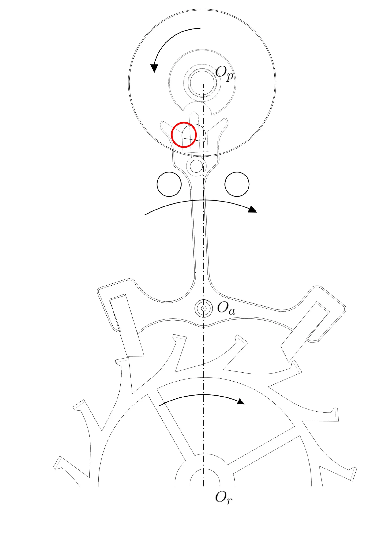
Figure 20
Impact at the start of the balance impulse
Click on the thumbnail to enlarge it
4. End of the drop
A tooth of the escape wheel comes into contact with the resting surface of a pallet stone of the pallets (lever) (Figure 21).
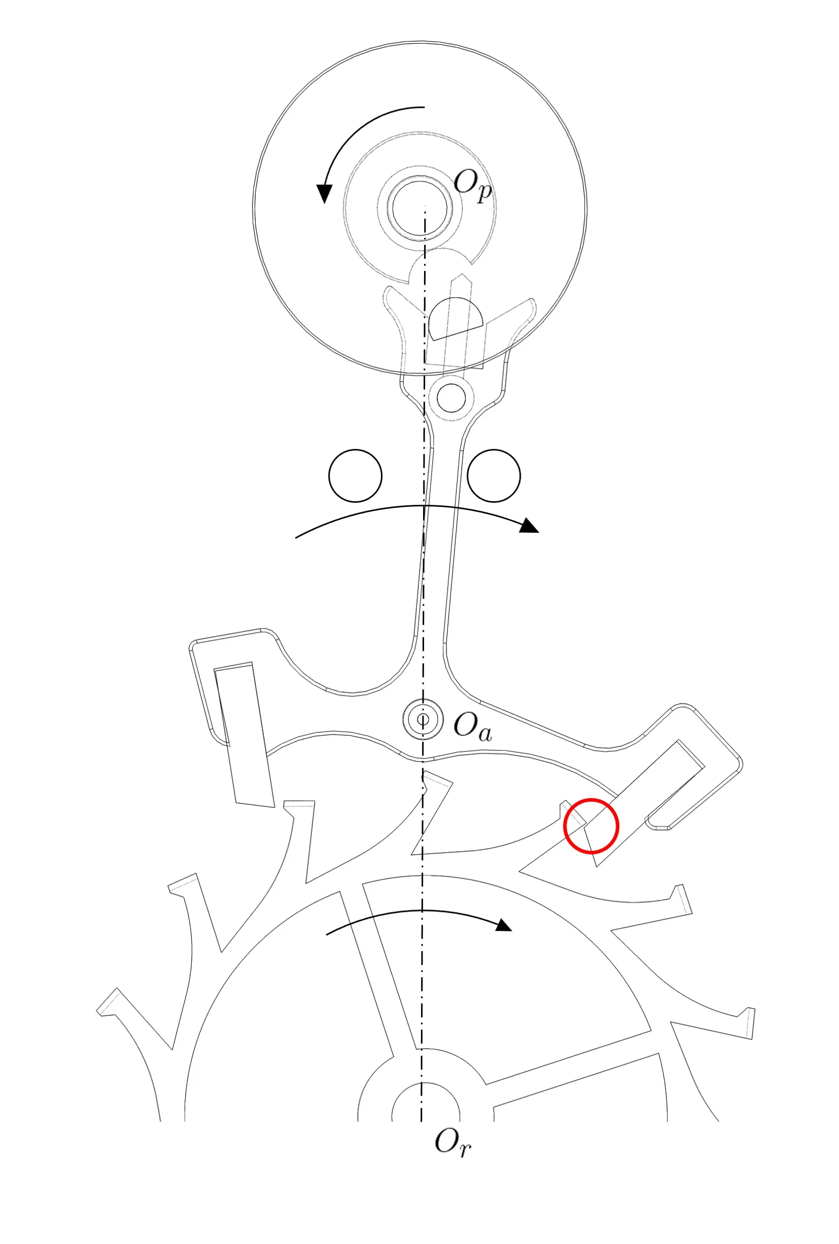
Figure 21
Shock at the end of the drop of the escape wheel
Click on the thumbnail to enlarge it
5. End of the backlash
Finally, at the end of its backlash, the rod (baguette shape) of the pallets (lever) comes into contact with one of the banking pins (or a limiting stop) (Figure 22).
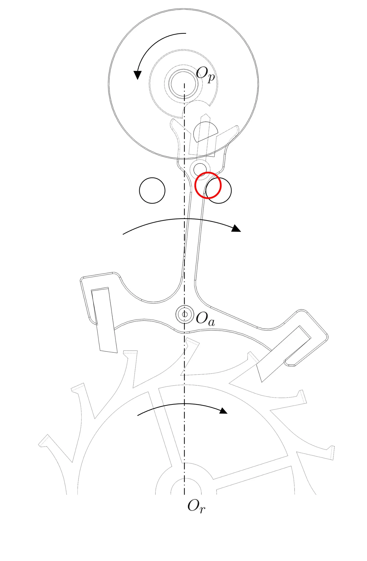
Figure 22
Shock at the end of the backlash of the pallets (lever)
Click on the thumbnail to enlarge it
10. Analysis of Timing Diagrams
Watch rate testing devices (timing machines), provide a great deal of information such as the instantaneous daily rate, the amplitude and the value of the guide mark. However, a good reading of the diagrams provided by timing machines makes it possible to identify many issues related to the finishing train, to the escapement and to the regulating organ.
Thus, during fault-free operation of a perfectly regulated watch, the diagram shows a single horizontal line (Figure 23).

Figure 23
When the guide mark is too large, two parallel lines appear on the diagram (Figure 24). The correction consists of adjusting the guide mark (via the movable stud holder or the collet), then readjusting the rate.

Figure 24
When the line of the diagram is ascending, the watch is running fast (Figure 25 left). Conversely, when it goes down, the watch runs slow (Figure 25 right). This then involves adjusting the rate (by modifying the active length of the hairspring or the moment of inertia of the balance).

Figure 25
In some cases, a variation in the rate will be observed during movement measurements, both in horizontal and vertical positions (Figure 26). The correction, in this case, consists of tightening the banking pins.

Figure 26
When the diagram shows a regular sinusoidal line, it is useful to measure the time interval between each peak of the sine wave. If the frequency corresponds to the rotation speed of the fourth wheel (seconds wheel) (60 sec if the movement has a Hand of seconds), an Out-of-flat (hairspring defect) or Out-of-round (hairspring defect) defect exists on the Fourth wheel (seconds wheel) (Figure 27). The correction then consists of checking and correcting the riveting of the seconds wheel on its pinion, or replacing the Fourth wheel (seconds wheel).

Figure 27
The diagram sometimes shows an irregular and random line. In such cases, the amplitude is often too low or subject to numerous variations (Figure 28). In such a case, it is recommended to carry out a complete overhaul of the movement.

Figure 28
If the diagram occasionally shows nearly vertical lines, if the sounds of the escapement speed up and become irregular, and a sharp increase in amplitude (or the total loss of amplitude information) is observed, this means that amplitude is occasionally too high and that the balance knock (rebate) (Figure 29). It is then possible to replace the mainspring with a spring developing a lower torque, or to modify the value of the total depth of the pallets of the pallets (lever).
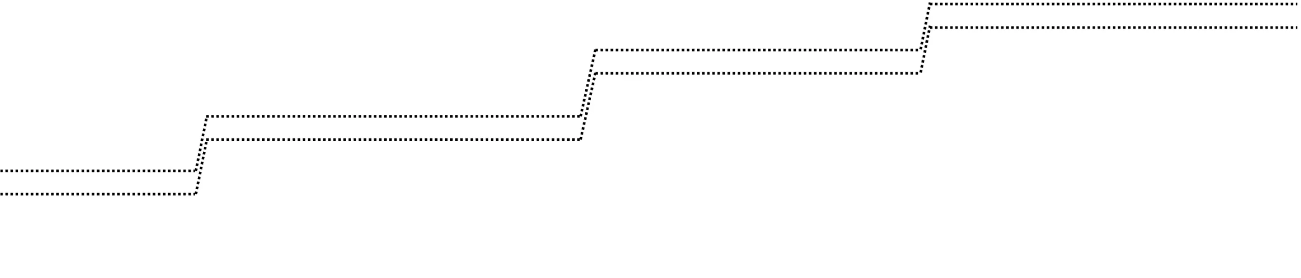
Figure 29
Multiple and irregular lines indicate that the balance knocks (rebate) continuously (amplitude too high) (Figure 30). Here again, the defect will be corrected by replacing the mainspring with a lower torque spring or by modifying the total depth of the pallet stones.

Figure 30
A diagram showing a sinusoidal curve with a tight frequency (a few seconds) indicates an out-of-round problem with the escape wheel (Figure 31). It is then recommended to replace the escape wheel.

Figure 31
If the diagram shows a random line superimposed on a straight line, this means that the entry Pallet stone of the Pallets (lever) is sticking or dirty (Figure 32). It is then recommended to carefully clean the pallets (lever) and the escape wheel, and, if necessary, to replace the Pallets (lever) or the entry Pallet stone.

Figure 32
The vertical lines marking a normal rate line indicate that the hairspring (balance spring) occasionally touches the regulator pins or the stud (Figure 33). This defect should be corrected by checking the geometry and centering of the hairspring.

Figure 33
A stabilization of the rate and of theamplitude that is too slow between two measurement positions indicates a problem withlubrication of the bearings of the balance or of the finishing Train (wheel train) (Figure 34).

Figure 34
11. The draw
The draw is a safety feature that keeps the Rod (baguette shape) of the pallets (lever) in contact against the banking pins when the balance performs its supplementary arc. This prevents the dart (safety pin) from coming into contact with the edge of the small roller and disturbing the period of the regulating organ.
The mechanical action of draw results from the pressure exerted by a tooth of the escape wheel on the resting surface of one or the other pallet stone of the pallets (lever).
Thus, the force F1 exerted by the wheel tooth acts perpendicular to the resting surface of the pallet stone and creates a moment of force through the lever arm of the distance d1 with the pivot point of the pallets (lever). This moment of force has the effect of pressing the rod (baguette shape) of the pallets (lever) against the banking pin with a force F2 and a lever arm d2, corresponding to the distance between the pivot point of the pallets (lever) and the center of the banking pin (Figure 35).
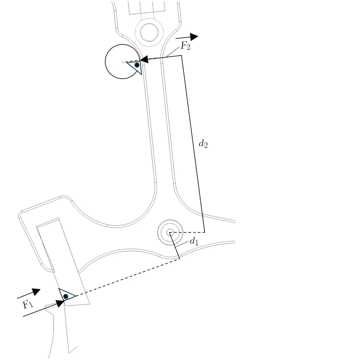
Figure 35
The Pallets (lever) is thus held in contact against the banking pin. If a shock manages to overcome the force of the draw, the Pallets (lever) will move and the Dart (safety pin) may briefly come into contact with the edge of the small roller table, but the force of the draw will immediately bring it back to its rest position.
Value of the draw’s moment of force
The moment of force of the draw can be defined by the following calculations:

The distance d1 varies according to the value of the angle α measured at the rest point B1. A variation of the angle α thus causes an increase or decrease in the moment of force M of the draw (Figure 36).
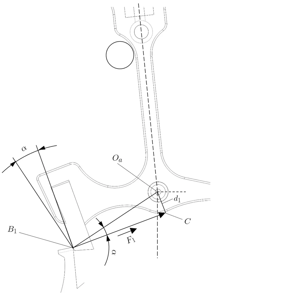
Figure 36
The draw angle β is the value between a perpendicular raised at the rest point B on the line joining this point to the pivot point of the pallets  and the rest plane of the pallet stone BP (Figure 37).
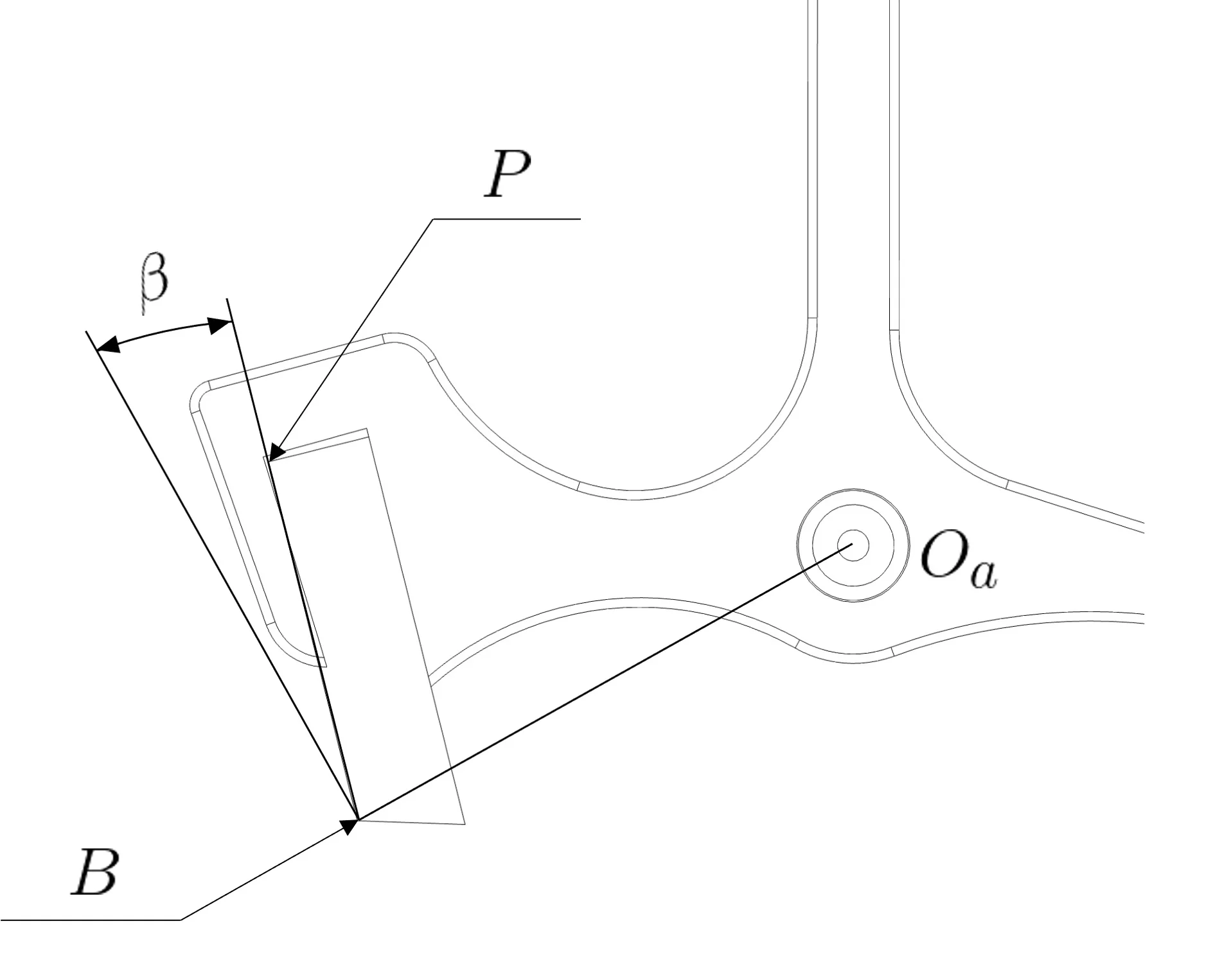
Figure 37
As we have just seen, the draw angle β is defined at the resting tip B of the Pallet stone. It can also be defined at the resting point B1 of the Pallet stone. In this case, the draw angle is called α (Figure 38). This makes it clear that during Unlocking (drop angle) (see operation), the draw angle varies from β to α.
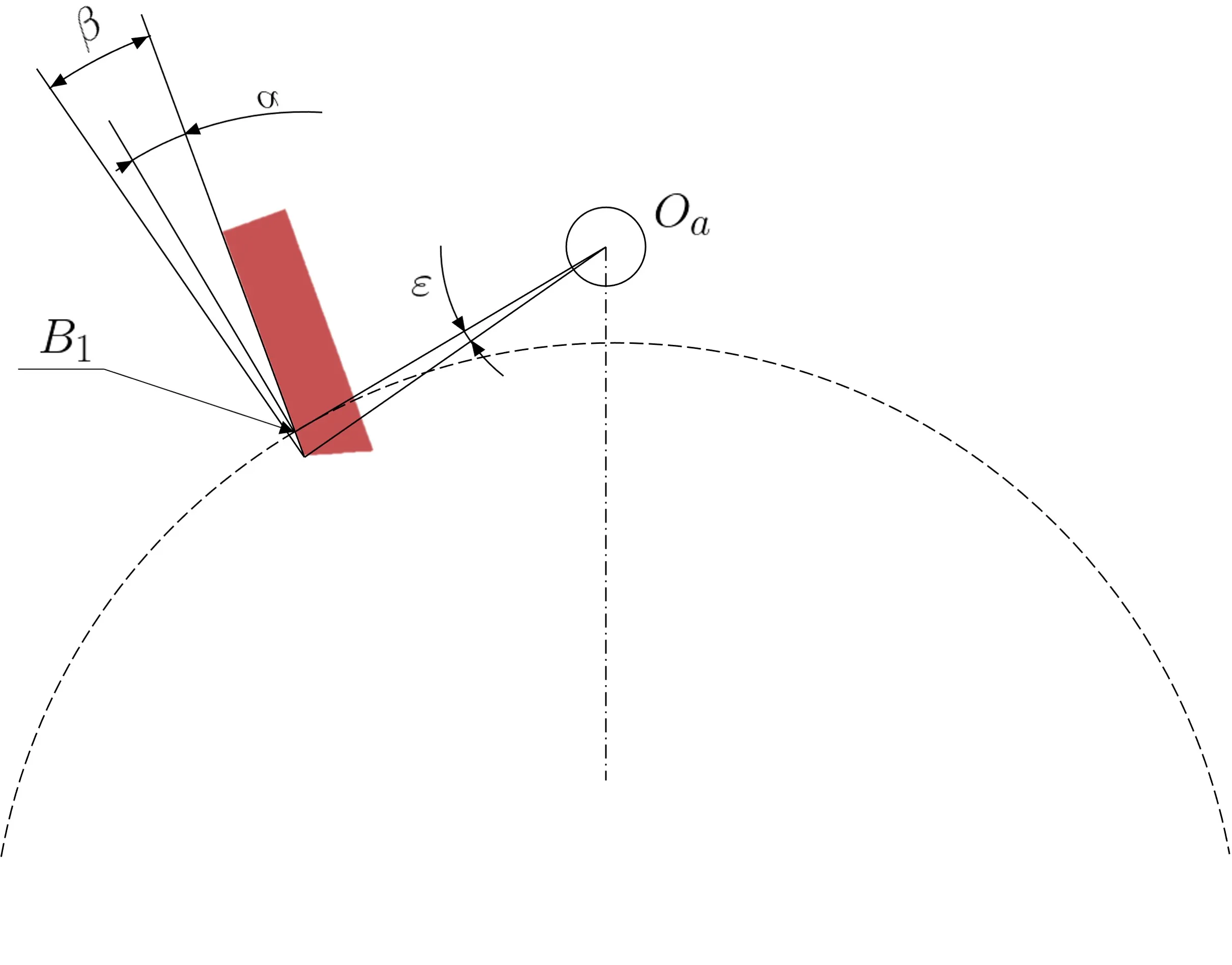
Figure 38
L’angle de tirage est défini lors de la construction de l’échappement (idéalement, il est de 9° pour la combinaison roue en acier- palette en rubis). Mais un angle de tirage trop faible diminue la force du tirage et en réduit donc la sécurité. Il accroît également le coefficient de frottement.
À l’inverse, un angle trop fort augmente le moment de force nécessaire au dégagement et augmente la valeur du recul de la roue d’échappement (perte de la valeur de l’impulsion). Ainsi, un angle de tirage trop faible ou trop élevé perturbe les qualités réglantes de l’organe régulateur. C’est ainsi qu’on peut définir un angle de tirage idéal (pour une roue d’échappement en acier et des palettes en rubis), généralement compris entre 13° et 16°.
Enfin, on notera que, lors du dégagement, l’angle de tirage augmente sur la palette d’entrée de l’angle ε (β = α + ε) (Figure 38).
Alors qu’il diminue sur la palette de sortie à la même valeur ε (β = α – ε) (Figure 39).
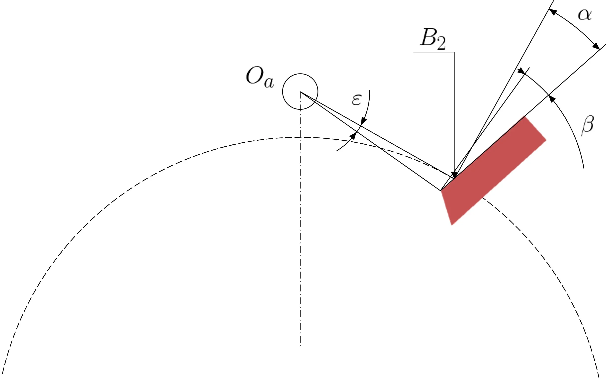
Figure 39
12. Stops on the rest and impulse planes
1. Stop on the rest plane
We observe the stop on the rest plane when the movement is fully wound. Then manually position the balance so that the impulse pin (roller jewel) is at the start of the unlocking (drop angle) phase (see “Operation”) (Figure 40).
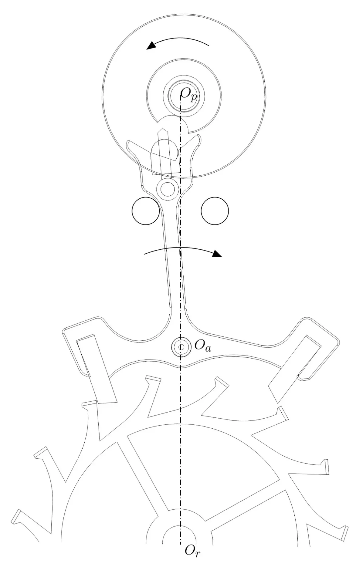
Figure 40
If the balance fails to unlock the escape wheel from the locking plane of the pallet stone by the force of the hairspring (balance spring), the movement is considered to have stopping on the resting surface.
Stopping on the resting surface is most pronounced when the movement is at maximum Winding, because the force exerted by the tooth of the Escape wheel on the resting surface of the Pallet stone (and therefore the draw) is then maximum. As we describe in the chapter “draw”, the draw increases during Unlocking (drop angle) on the Entry pallet stone and decreases during Unlocking (drop angle) on the exit pallet stone.
Movements with a diameter greater than 24 mm must under no circumstances exhibit stopping on the resting surface. However, stopping on the resting surface cannot be prevented when it comes to a movement with a diameter of less than 24 mm. Indeed, when the size of the movement decreases, the Moment of inertia and the torque of the Hairspring (balance spring) decrease more quickly than the torque of the mainspring.
In movements with a diameter of less than 24 mm, it is not tolerated to have a stop on the resting plane after 24 h of running, as the difficulty in operating the unlocking significantly disturbs the isochronism of the regulating organ.
1a. Causes of the stop on the resting plane
The causes of a stop on the resting plane can be as follows:
- a lack of freedom or an insufficient lubrication of the escapement wheels. (noticeable by a amplitude that is too low)
- a defective surface condition of the resting plane of one or the other of the pallet stones or insufficient lubrication of the escape wheel by the pallet stones.
- A defective profile or surface finish of the resting plane of the Escape wheel teeth.
- A drop angle that is too strong.
- A lack of Shake (play) of the Impulse pin (roller jewel) in the Fork of the Pallets (lever).
- Sides of the Entry of the Fork that are too short, resulting in dart (safety pin) Shake (play) that is too great at the start of the supplementary arc of the Balance.
- A poor setting of the Guide mark
To avoid or limit stopping on the resting plane (depending on the diameter of the Movement), the position of the Balance when the stop on the resting plane occurs must be determined. It is then possible to reduce the Total depth of each Pallet stone in order to angularly shift the end of the Unlocking (drop angle) so that it occurs before the stopping position on the resting plane. This solution, however, involves a reduction in the value of the Backlash.
Another solution, more complicated to implement, consists in increasing the inclination of the impulse planes of the pallet stones. This will reduce the value of the total depth without modifying the angle of the backlash. Care must then be taken to maintain a sufficient value of the virtual depths.
When developing small-diameter movements, the stop on the rest plane can be minimized by increasing the ratio between the lift angles of the pallets (lever) and the balance (see table below). This implies reducing the diameter of the rollers and lengthening the fork of the pallets (lever). Thus, the balance begins its unlocking (drop angle) with a larger angle than that of the dead point, which increases its torque and limits the stop on the rest plane. However, a high lift angle of the balance increases the disruptive influence of the escapement on the isochronism of the regulating organ.
2. Stop on the impulse plane
We observe the stopping on the impulse plane by winding the mainspring by two teeth of ratchet wheel. We then manually position the balance so that one of the teeth of the escape wheel is at the beginning of the impulse plane of the pallet stone (Figure 41). If the impulse is not fully given by this weak driving force, then the movement is considered to have stopping on the impulse plane.
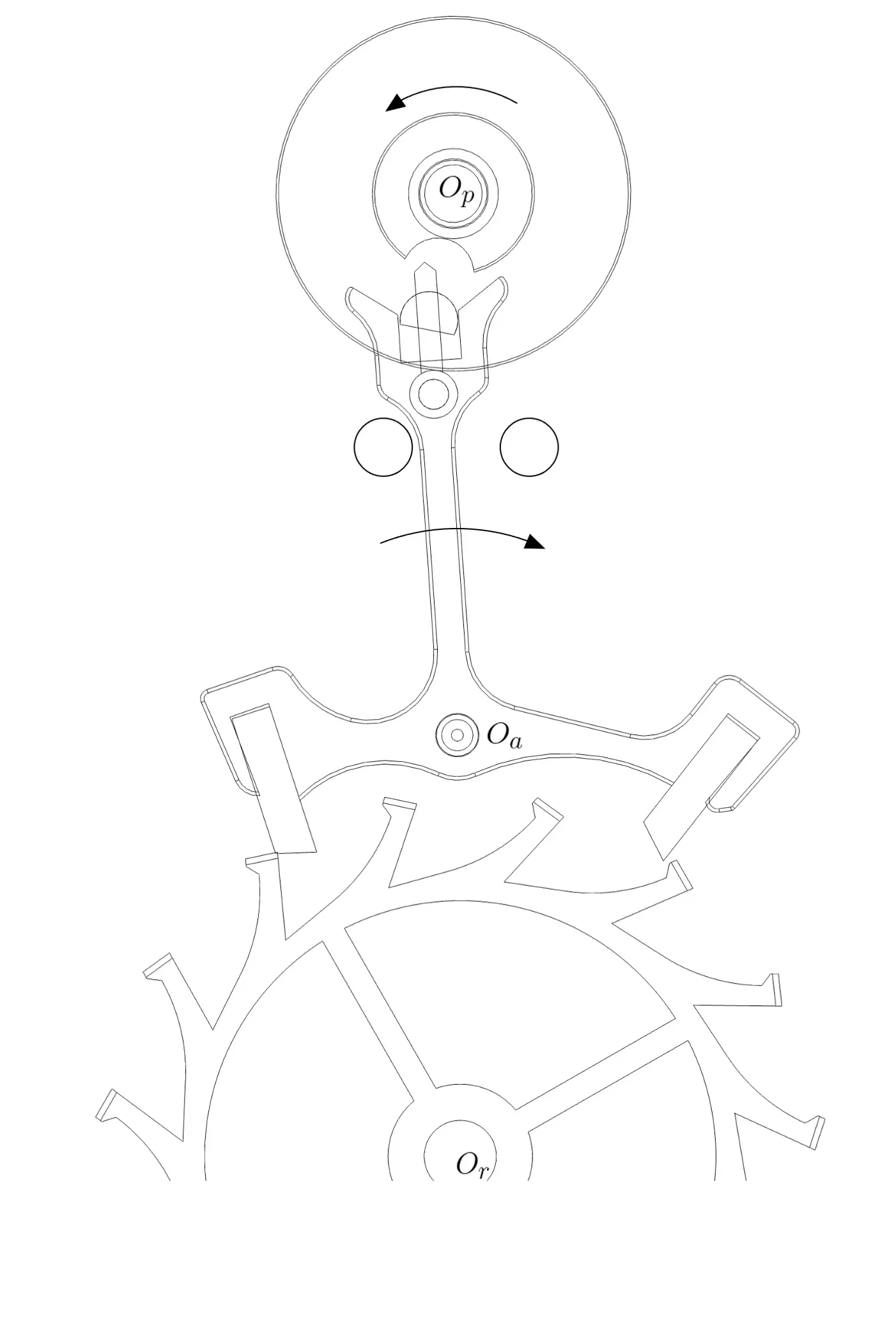
Figure 41
All movements have stopping on the impulse plane. To check whether this is acceptable, the mainspring is wound very gradually until the movement starts spontaneously, taking care to observe the rotation of the ratchet wheel. The accepted values for overcoming stopping on the impulse plane are as follows:
Small diameter Movements: starts running after 4 to 5 teeth of Winding of the Ratchet wheel.
Medium diameter Movements: starts running after 1/2 turn of Winding of the Ratchet wheel.
Large diameter Movements: starts running after 1 to 2 turns of Winding of the Ratchet wheel.
2.a Causes of stopping on the Impulse plane
The causes of stopping on the Impulse plane may be as follows:
- A lack of driving force (Mainspring too weak, lack of freedom in the finishing Train, gearing defects, poor Lubrication).
- A lack of freedom of the Pallets (lever) or the Balance.
- A defective surface condition or profile of the Impulse plane of the Pallet stone.
- A surface finish or profile issue on the impulse plane of the escape wheel teeth.
- Poor lubrication of the escape wheel – pallets (lever).
- A lack of shake (play) of the impulse pin (roller jewel) in the fork of the pallets (lever).
- A defective surface finish or profile of the entry of the fork of the pallets (lever).
- Poor alignment of the guide marks.
Important
The stop on the impulse plane increases as the diameter of the movement increases. This is not actually a defect, as it does not affect either the precision of the movement or the isochronism of the regulating organ. However, when it is too significant, it does not allow the movement to start spontaneously, under the sole influence of the driving force, and requires manually giving a first impulse to the balance (by rapid rotation of the movement, of the watch for example).
To achieve the best regulation and the best possible isochronism, it is preferable to have the lowest possible lift angle of the balance.
3. Accepted values & ratios of lift angles

This page has been automatically translated from the French reference version using an artificial intelligence tool. Errors or inaccuracies may remain. If you notice any, especially if this is your native language, please feel free to report them to info@horopedia.org. Your contribution helps us improve the quality of the encyclopedia.
While awaiting their translation, images and videos will temporarily remain displayed in French.
Thank you for your understanding.